
Modular device & interface design

A technology of interface device and osseointegration, applied in medical science, prosthesis, artificial arm, etc., can solve the problems of failing to show the mechanical robustness of skin implantation activity

Inactive Publication Date: 2018-10-23
BIOS HEALTH LTD
View PDF12 Cites 2 Cited by
  • Summary
  • Abstract
  • Description
  • Claims
  • Application Information

AI Technical Summary

Problems solved by technology

While reducing the risk of infection, these systems often fail to demonstrate long-term skin implant activity or demonstrable mechanical robustness
[0006] In addition, these systems have the major disadvantage of often requiring multiple surgeries on the patient; for example, the patient typically requires the first surgery to create the stump; Healed, will undergo further surgery to accommodate further rods that can be paired with already implanted rods that protrude through the skin
Not uncommonly multiple further corrective surgeries are required

Method used


Image

  • Modular device & interface design
  • Modular device & interface design
  • Modular device & interface design

Examples


Embodiment Construction

[0080] Reference will now be made in detail to various aspects and / or embodiments, examples of which are illustrated in the accompanying drawings. In the following detailed description, numerous specific details are set forth in order to provide a thorough understanding of the present invention. It will be apparent, however, to one of ordinary skill in the art that any number of these specific details may be utilized without and / or from one or more embodiments, unless otherwise noted herein. to practice the present invention.

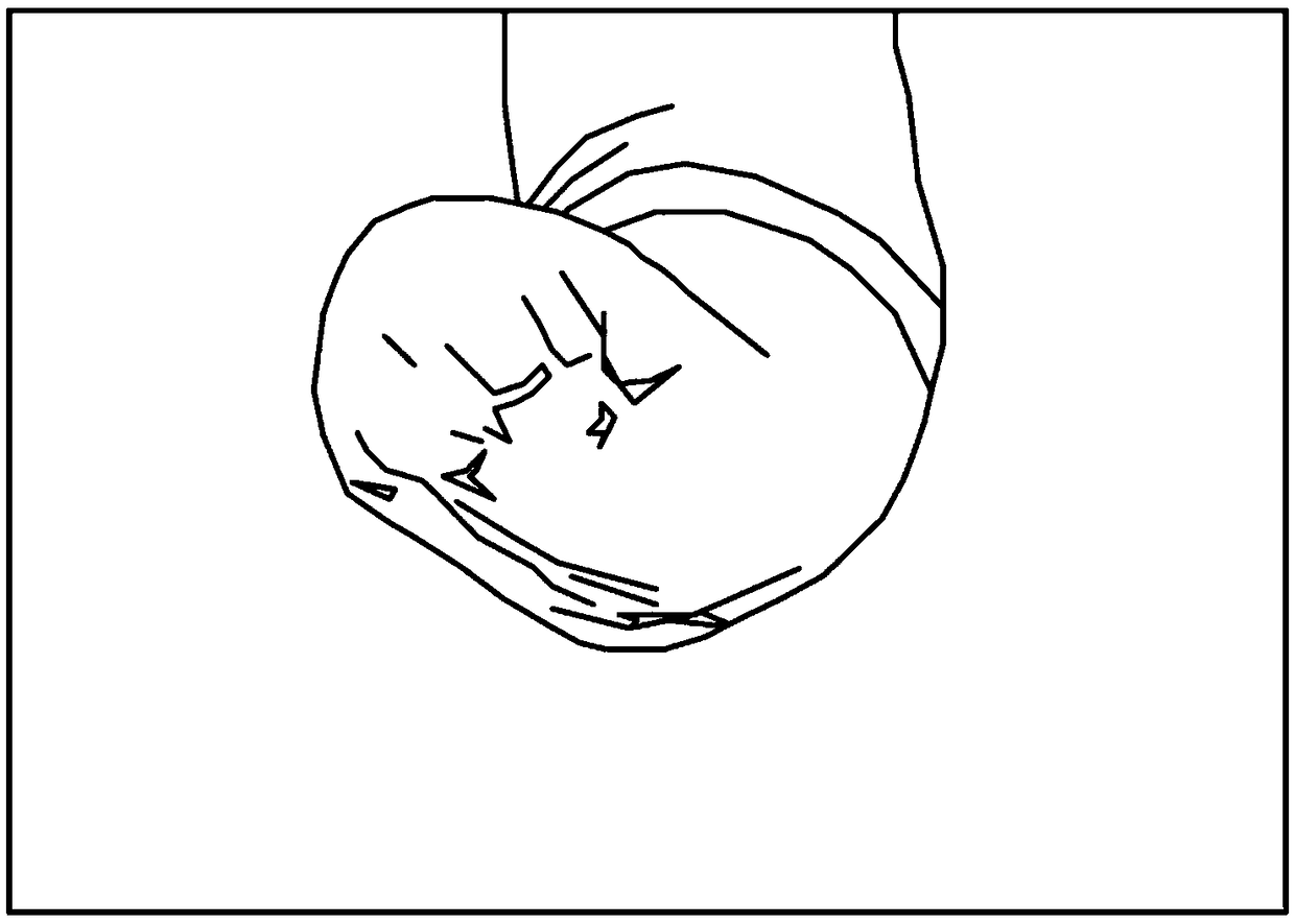
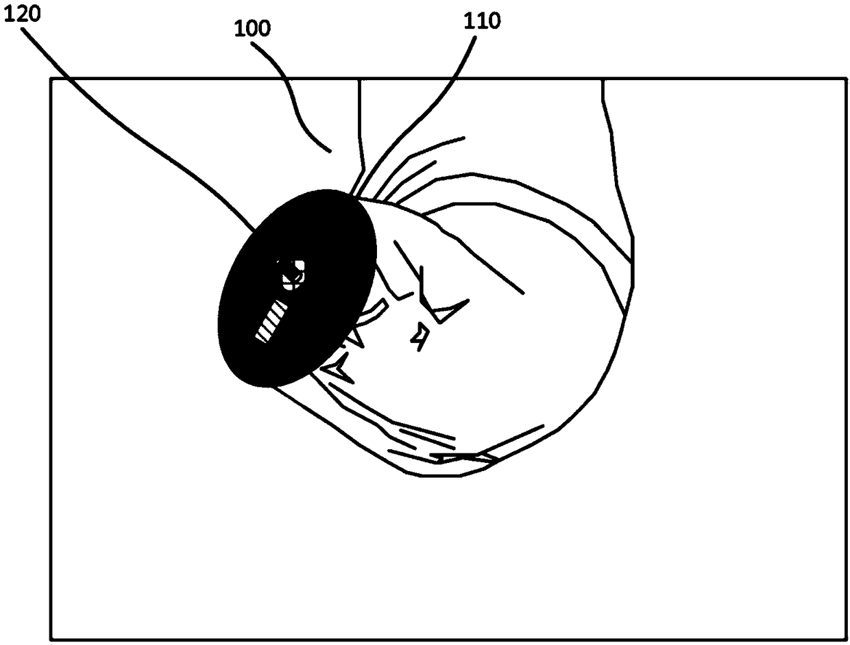
[0081] Figure 1A and 1B Photographs of the amputated limb without the prosthetic interface device fitted thereto and / or before and after, respectively. The terms "prosthetic" and "prosthetic" are used throughout and should be construed broadly to include any device intended to replace a missing or damaged part of the body or to make a part of the body work better, and includes, but is not limited to bionic limbs etc. Furthermore, the terms "patient...


PUM

PropertyMeasurementUnit
Lengthaaaaaaaaaa

Abstract

Herein described is an osseointegrated interface device for engagement with an amputated limb including the skin comprising: a cap portion engageable with an osseointegrated device; wherein the cap portion comprises a surrounding flange; and wherein in use the surrounding flange receives the skin of the amputated limb at a distance spaced from the osseointegrated device.

Description

technical field [0001] The invention relates to a prosthesis interface device. In particular, the present invention provides an osseointegrated prosthetic interface device for permanent or semi-permanent fitting to the extremity of a patient's limb to enable attachment to any future prosthesis. Background technique [0002] Amputation is often performed to save the remainder of a limb where injury or disease threatens the viability of the limb itself. It is thought that amputation rates may increase due to the general increase in rates of diabetes and obesity. [0003] Traditionally for amputees, prosthetic limbs are provided to address some functional and / or aesthetic issues of the patient. These prosthetics are usually attached to the amputated limb through a cup / socket device. While generally addressing the patient's aesthetic concerns, these systems / devices often fail to provide the patient with the strength required for adequate functional use due to the functional w...

Claims


Application Information

Patent Timeline
IPC IPC(8): A61F2/54
CPCA61F2/54A61F2/70A61F2/72A61F2/80A61L27/12A61F2002/7887A61L2300/412
Inventor O.阿米塔格
Owner BIOS HEALTH LTD
Learn More