Imaging lens
一种摄像镜头、透镜的技术,应用在摄像镜头领域,达到高分辨率、低F值的效果
- Summary
- Abstract
- Description
- Claims
- Application Information
AI Technical Summary
Problems solved by technology
Method used
Image

Examples
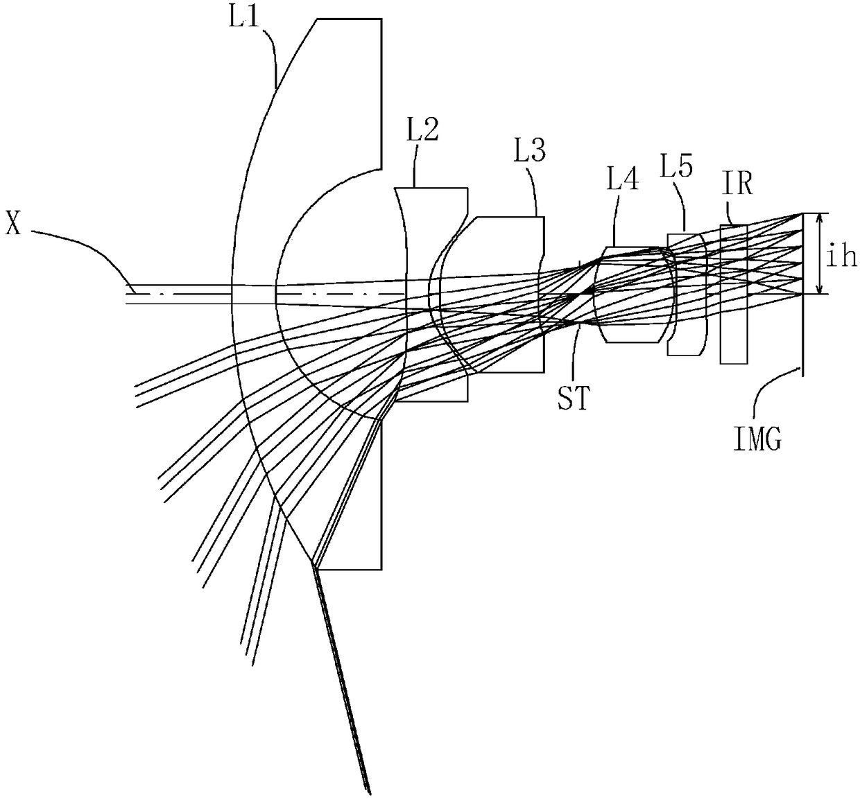
Embodiment 1
[0155] Basic lens data are shown in Table 1 below.
[0156] [Table 1]
[0157] Example 1
[0158] unit mm
[0159] f=0.91
[0160] Fno=2.0
[0161] ω(°)=103.3
[0162] ih=1.85
[0163] TTL=12.78
[0164] surface data
[0165]
[0166] Composition Lens Data
[0167]
[0168] Aspheric data
[0169]
[0170] The imaging lens of Example 1 satisfies conditional expressions (1) to (10) as shown in Table 9.
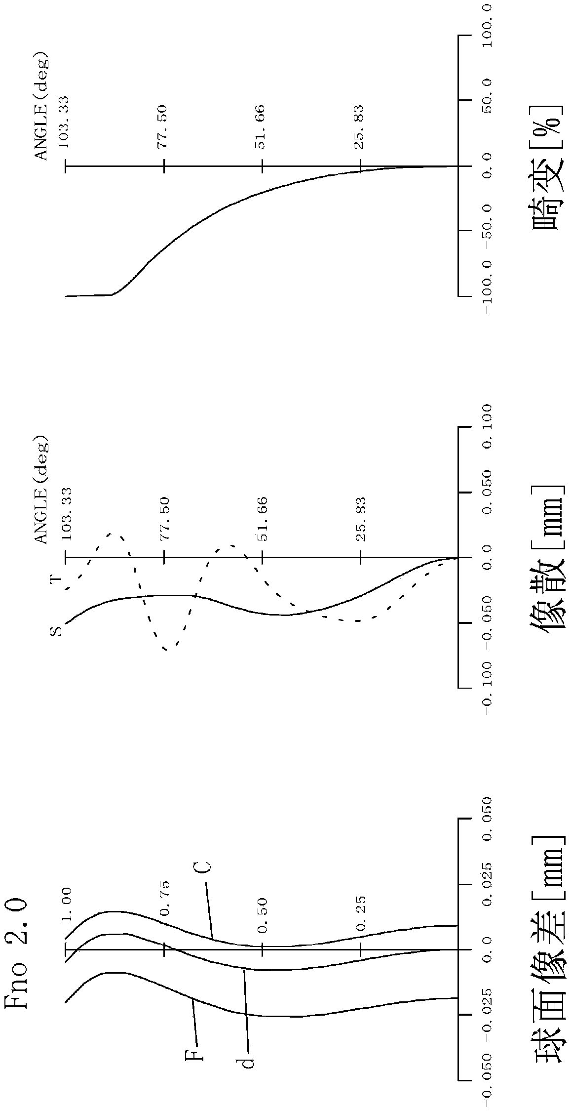
[0171] figure 2 For the imaging lens of Example 1, spherical aberration (mm), astigmatism (mm), and distortion (%) are shown. The spherical aberration diagram shows the amount of aberration for each wavelength of F-line (486 nm), d-line (588 nm), and C-line (656 nm). In addition, the astigmatism diagram shows the aberration amount (solid line) on the d-line on the sagittal image plane S and the aberration amount (dotted line) on the d-line on the meridian image plane T (dotted line) ( Figure 4 , Figure 6 , Figure 8 , Figure 10 , Figure 12 , Figu...
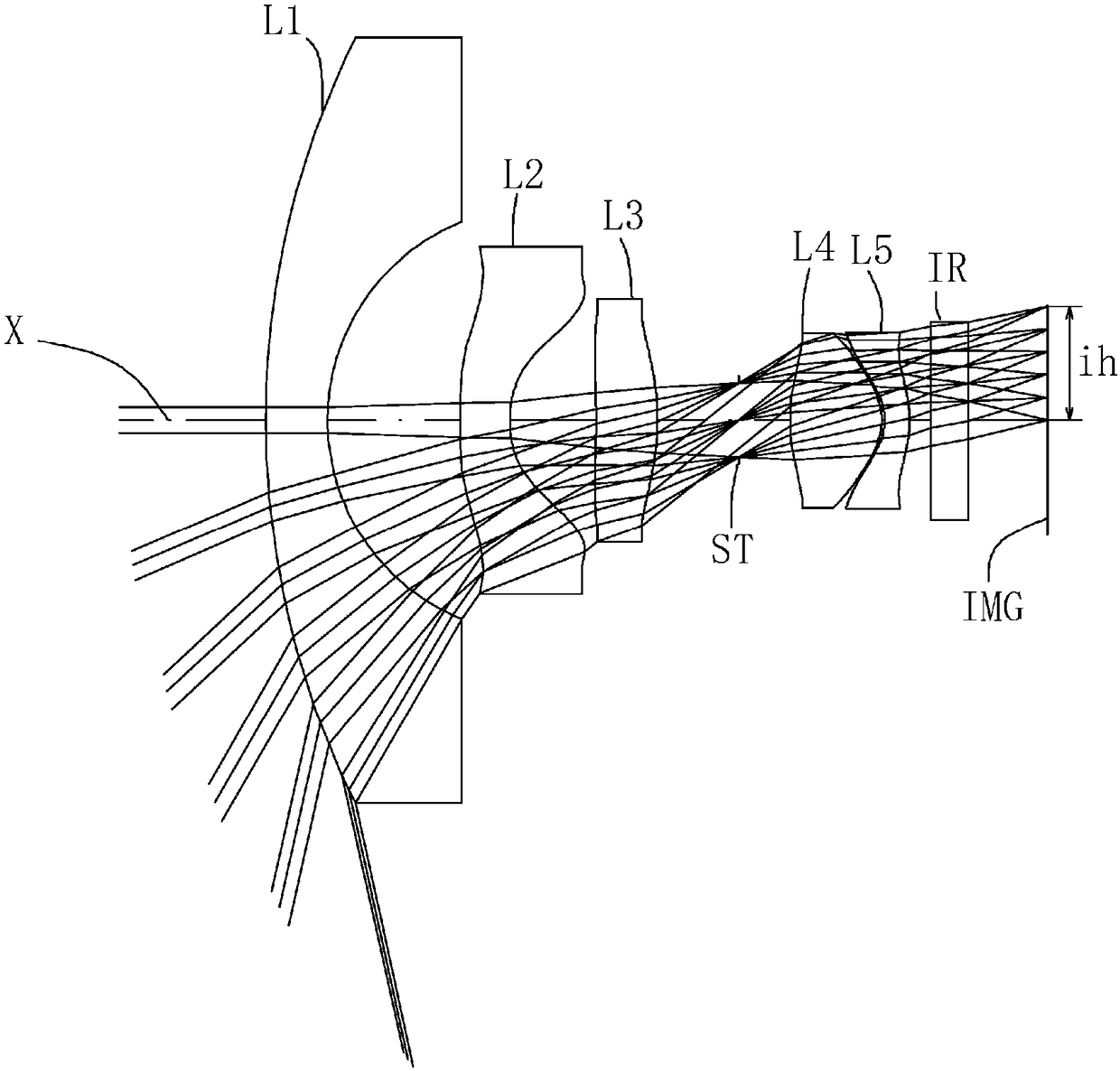
Embodiment 2
[0173] Basic lens data are shown in Table 2 below.
[0174] [Table 2]
[0175] Example 2
[0176] unit mm
[0177] f=0.87
[0178] Fno=2.0
[0179] ω(°)=102.5
[0180] ih=1.85
[0181] TTL=12.45
[0182] surface data
[0183]
[0184] Composition Lens Data
[0185]
[0186] Aspheric data
[0187]
[0188] The imaging lens of Example 2 satisfies conditional expressions (1) to (10) as shown in Table 9.
[0189] Figure 4 For the imaging lens of Example 2, spherical aberration (mm), astigmatism (mm), and distortion (%) are shown. Such as Figure 4 As shown, it can be seen that various aberrations are well corrected.
Embodiment 3
[0191] Basic lens data are shown in Table 3 below.
[0192] [table 3]
[0193] Example 3
[0194] unit mm
[0195] f = 0.90
[0196] Fno=2.0
[0197] ω(°)=101.7
[0198] ih=1.85
[0199] TTL=12.77
[0200] surface data
[0201]
[0202] Composition Lens Data
[0203]
[0204] Aspheric data
[0205]
[0206] The imaging lens of Example 3 satisfies conditional expressions (1) to (10) as shown in Table 9.
[0207] Figure 6 For the imaging lens of Example 3, spherical aberration (mm), astigmatism (mm), and distortion (%) are shown. Such as Figure 6 As shown, it can be seen that various aberrations are well corrected.
PUM
 Abstract
Description
Claims
Application Information
 - Generate Ideas
- Intellectual Property
- Life Sciences
- Materials
- Tech Scout
- Unparalleled Data Quality
- Higher Quality Content
- 60% Fewer Hallucinations
Browse by: Latest US Patents, China's latest patents, Technical Efficacy Thesaurus, Application Domain, Technology Topic, Popular Technical Reports.
© 2025 PatSnap. All rights reserved.Legal|Privacy policy|Modern Slavery Act Transparency Statement|Sitemap|About US| Contact US: help@patsnap.com