Food processing machine
A technology for food processing machines and small spaces, which can be applied to home appliances, applications, kitchen utensils, etc. It can solve the problems of automatic cleaning of soybean milk machines, inconvenient cleaning, and scald users, etc., so as to reduce the effect of flow aggregation and high crushing efficiency , the effect of reducing kinetic energy loss
- Summary
- Abstract
- Description
- Claims
- Application Information
AI Technical Summary
Problems solved by technology
Method used
Image
Examples
Embodiment 1
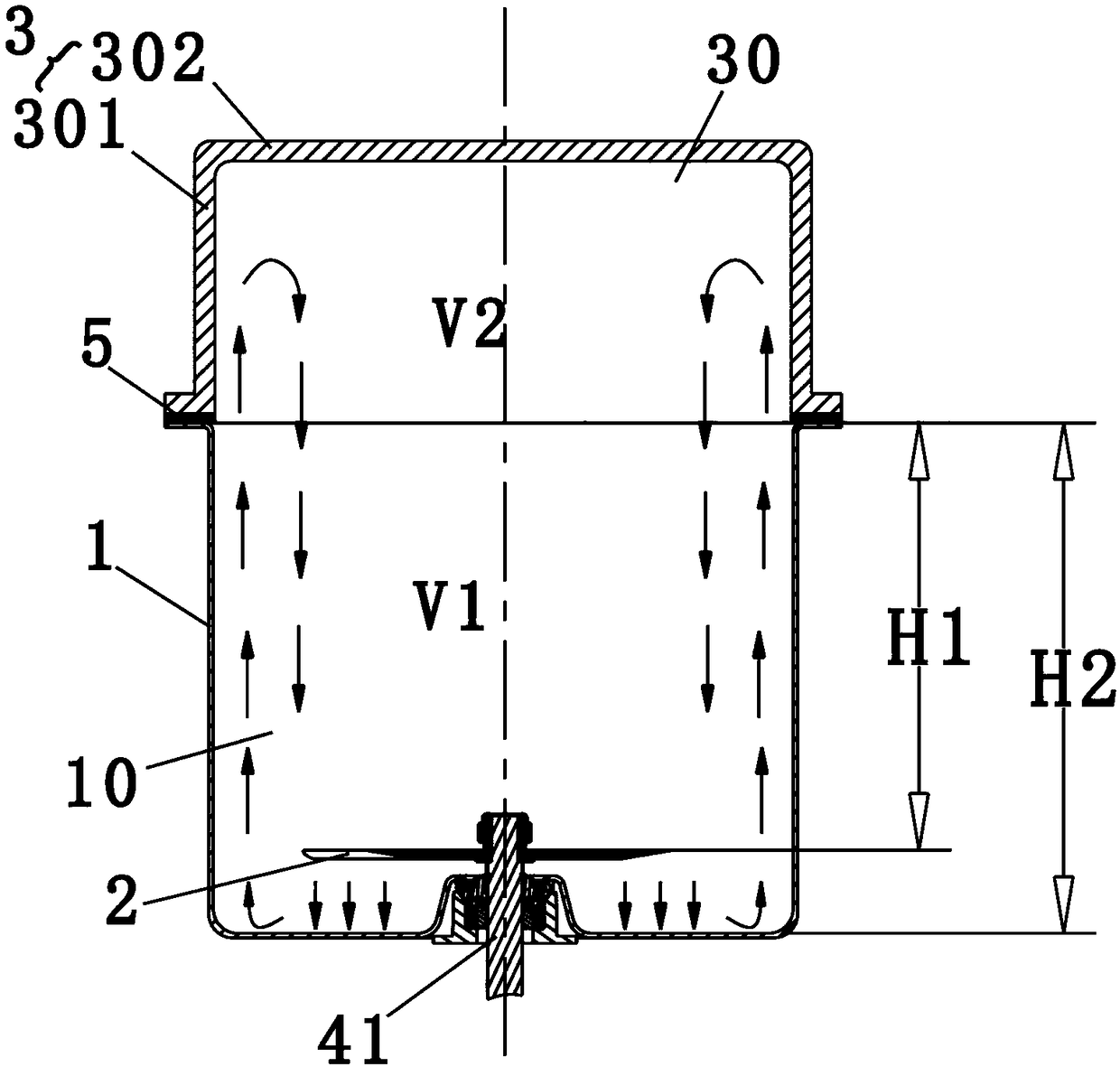
[0032] like figure 1 , figure 2 Shown is a schematic structural diagram of the first embodiment of the present invention. A food processor, comprising a small-space crushing cup 1, a crushing blade 2 mounted on the end of a rotating shaft 41 and a cup cover 3 mounted on the top of the small-space crushing cup 1, the rotating shaft 41 is driven by a motor (not shown in the figure) drive, and the crushing blade 2 is located in the crushing cavity 10 formed by the small space crushing cup 1, and a seal 5 at the sealing fit is arranged between the small space crushing cup 1 and the cup cover 3, and the small space crushing The volume V1 of the cup 1 is not greater than 1000mL. The bottom of the cup cover 3 is formed with an upwardly recessed auxiliary chamber 30. The auxiliary chamber 30 is surrounded by the crushing chamber 10 to form a slurry container. When the food processor is working, the small space inside the cup 1 The liquid rushes into the auxiliary chamber 30 along t...
Embodiment 2
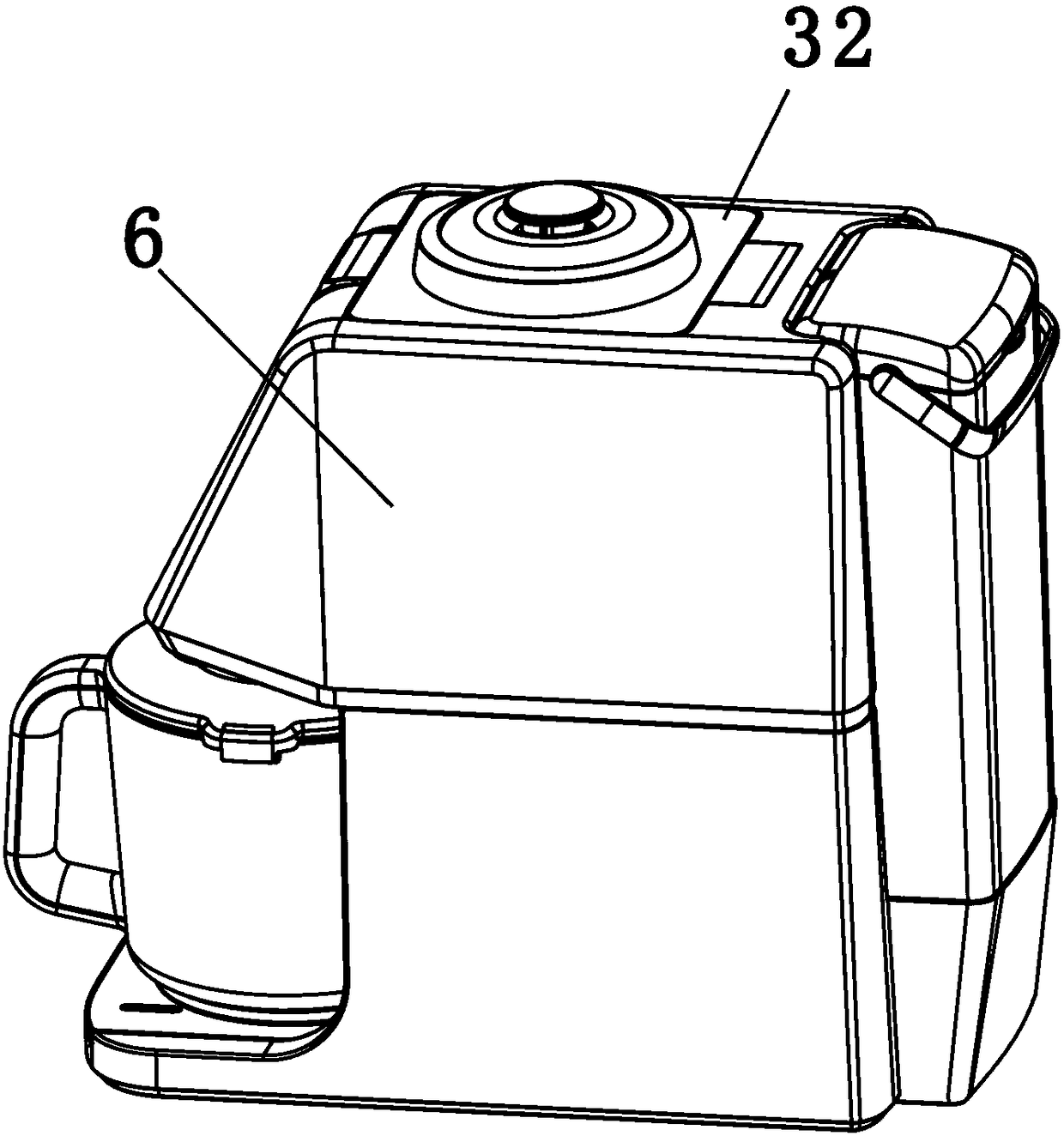
[0042] like image 3 , Figure 4 Shown is a schematic structural diagram of the second embodiment of the present invention. In this embodiment, the food processor includes a base 6, the small-space crushing cup 1 is fixed inside the base 6, and one end of the cup cover 3 is hinged and fixed to the base 6 (not shown in the figure). And the cup cover 3 can be rotated around the hinge to open the crushing cup 1 in a relatively small space, and the cup cover 3 can be detached from the base 6 .
[0043] In addition, the top wall of the auxiliary chamber is provided with an exhaust passage 31 protruding into the auxiliary chamber. The exhaust passage 31 communicates with the outside atmosphere, and the outside of the exhaust passage 31 is in the shape of a trumpet with a large bottom and a small top. Structure, the outer peripheral wall of the cup cover 3 is also provided with an outwardly extending annular flat plate 32, the annular flat plate 32 is flush with the top of the base...
Embodiment 3
[0047] like Figure 5 Shown is a schematic structural view of the third embodiment of the present invention. The difference between this embodiment and Embodiment 2 is that: in this embodiment, an exhaust through hole 33 is provided on the top wall of the auxiliary chamber, and an exhaust cover 34 is installed on the exhaust through hole 33, and the exhaust The gas cover 34 has a hollow exhaust column 35 extending into the exhaust through hole 33, and the exhaust port 36 is provided on the peripheral wall of the exhaust column 35 to communicate with the outside atmosphere, and the gas in the slurry container can pass through the hollow. The exhaust column 35 and the exhaust port 36 of the exhaust gas are discharged to the external atmosphere, and because the joint between the small-space crushing cup and the cup cover is sealed, even when the crushing blade is beating at a high speed, the splashed slurry is not easy to pass through the exhaust directly. The air column 35 and ...
PUM
 Abstract
Description
Claims
Application Information
 - R&D Engineer
- R&D Manager
- IP Professional
- Industry Leading Data Capabilities
- Powerful AI technology
- Patent DNA Extraction
Browse by: Latest US Patents, China's latest patents, Technical Efficacy Thesaurus, Application Domain, Technology Topic, Popular Technical Reports.
© 2024 PatSnap. All rights reserved.Legal|Privacy policy|Modern Slavery Act Transparency Statement|Sitemap|About US| Contact US: help@patsnap.com


