
Servo driver stroke calibration method and device

A technology of servo drive and calibration method, which is applied in the direction of instruments, program control, electrical program control, etc., can solve the problems of obtaining drives, insufficient linearity, and deviations in the corresponding relationship of position sensors, so as to improve control accuracy and overcome linearity poor effect

Active Publication Date: 2018-10-19
BEIJING INSPIRE ROBOTS TECH CO LTD
View PDF5 Cites 6 Cited by
  • Summary
  • Abstract
  • Description
  • Claims
  • Application Information

AI Technical Summary

Problems solved by technology

[0002] The control accuracy of the servo drive largely depends on the feedback accuracy of the position sensor. The feedback accuracy of the position sensor is affected by many factors, such as the linearity between the feedback value of the position sensor and the actual stroke of the servo drive is not high enough, the assembly process of the servo drive The installation difference in the center leads to deviations in the corresponding relationship between the feedback data of the position sensor and the actual stroke of the servo drive, etc.
[0003] In view of the low feedback accuracy of the position sensor, it will not be possible to obtain the accurate actual stroke of the drive based on the feedback data of the position sensor. It is urgent to provide a method for calibrating the stroke of the servo drive to overcome the poor linearity of the position sensor itself and installation differences. The resulting control error

Method used


Image

  • Servo driver stroke calibration method and device
  • Servo driver stroke calibration method and device
  • Servo driver stroke calibration method and device

Examples


Embodiment Construction

[0049] The following will clearly and completely describe the technical solutions in the embodiments of the present invention with reference to the accompanying drawings in the embodiments of the present invention. Obviously, the described embodiments are only some, not all, embodiments of the present invention. Based on the embodiments of the present invention, all other embodiments obtained by persons of ordinary skill in the art without making creative efforts belong to the protection scope of the present invention.

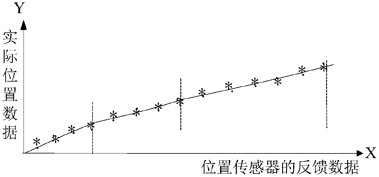
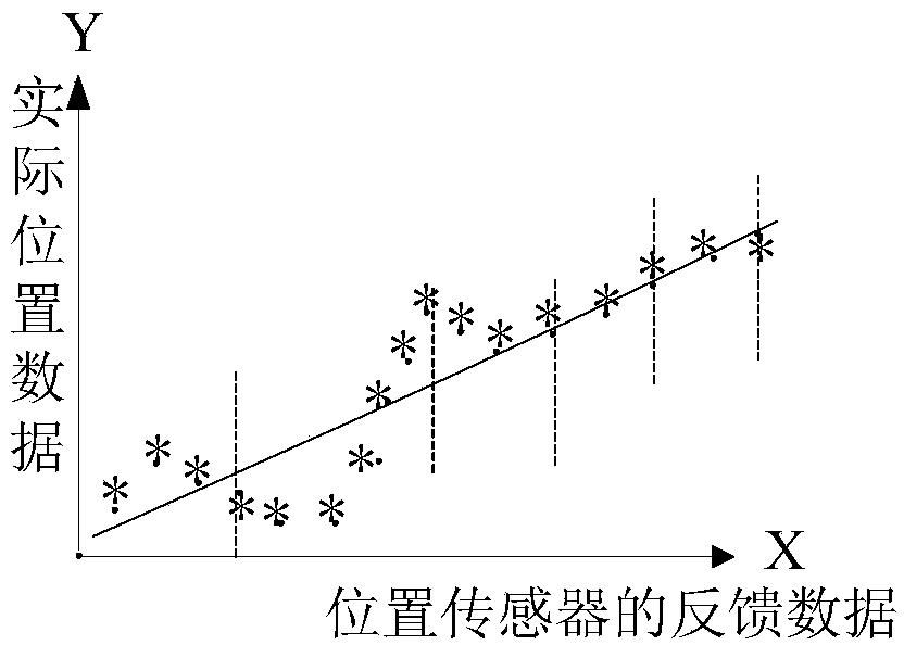
[0050]The stroke of the servo drive is determined by the feedback data of the position sensor. Ideally, the relationship between the servo drive and the position sensor is linear. The feedback value of the sensor increases by 200, the stroke of the servo driver increases by 30mm, and the feedback value of the position sensor increases by 300, but the actual situation is not the case. It is possible that the stroke of the servo driver increases by 10mm, the feed...


PUM


Abstract

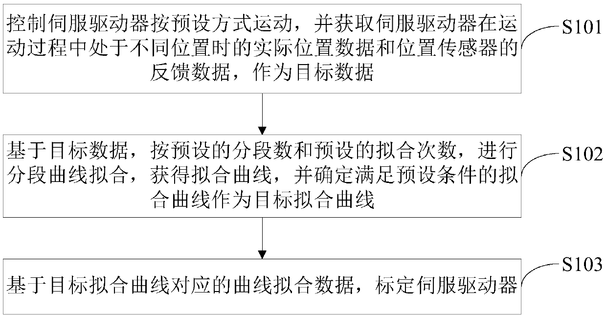
The application provides a servo driver stroke calibration method and device; the method comprises the following steps: controlling a servo driver to move in a preset mode, obtaining real position data of the servo driver in different positions in a motion process and feedback data of a position sensor, and using said data as target data; using the target data to carry out segmented curve fittingaccording to a preset segment number and a preset fitting number, obtaining fitting curves, and determining fitting curves satisfying preset conditions as target fitting curves; calibrating the servodriver according to curve fitting data corresponding to the target fitting curves. The servo driver stroke calibration method and device can effectively solve the control errors caused by self linearity difference and installation difference of the position sensor, thus improving the control precision of the servo driver.

Description

technical field [0001] The invention relates to the technical field of equipment calibration, in particular to a method and device for calibration of a stroke of a servo driver. Background technique [0002] The control accuracy of the servo drive largely depends on the feedback accuracy of the position sensor. The feedback accuracy of the position sensor is affected by many factors, such as the linearity between the feedback value of the position sensor and the actual stroke of the servo drive is not high enough, the assembly process of the servo drive The installation difference in the motor leads to deviations in the corresponding relationship between the feedback data of the position sensor and the actual stroke of the servo drive. [0003] In view of the low feedback accuracy of the position sensor, it will not be possible to obtain the accurate actual stroke of the driver based on the feedback data of the position sensor. It is urgent to provide a method for calibratin...

Claims


Application Information

Patent Timeline
Patent Type & Authority Applications(China)
IPC IPC(8): G05B19/414
CPCG05B19/414G05B2219/37542
Inventor 张健马志强
Owner BEIJING INSPIRE ROBOTS TECH CO LTD
Learn More