
Swirl trapped vortex type combustion chamber of micro-turbine engine

A technology for gas turbines and engines, applied in combustion chambers, continuous combustion chambers, combustion methods, etc., can solve problems such as shortened airflow retention time and reduced combustion performance of combustion chambers, and achieve reduced fuel consumption, improved combustion efficiency, and high-temperature areas The effect of reducing uneven distribution

Inactive Publication Date: 2018-10-19
NORTHWESTERN POLYTECHNICAL UNIV
View PDF6 Cites 6 Cited by
  • Summary
  • Abstract
  • Description
  • Claims
  • Application Information

AI Technical Summary

Problems solved by technology

Due to the small geometric size of the combustion chamber, the residence time of the airflow in the combustion chamber is shortened, which reduces the combustion performance of the combustion chamber, and the gas has already flowed out of the combustion chamber when the fuel cannot be fully combusted.

Method used


Image

  • Swirl trapped vortex type combustion chamber of micro-turbine engine
  • Swirl trapped vortex type combustion chamber of micro-turbine engine

Examples


Embodiment Construction

[0020] The present invention will be further described now in conjunction with accompanying drawing:

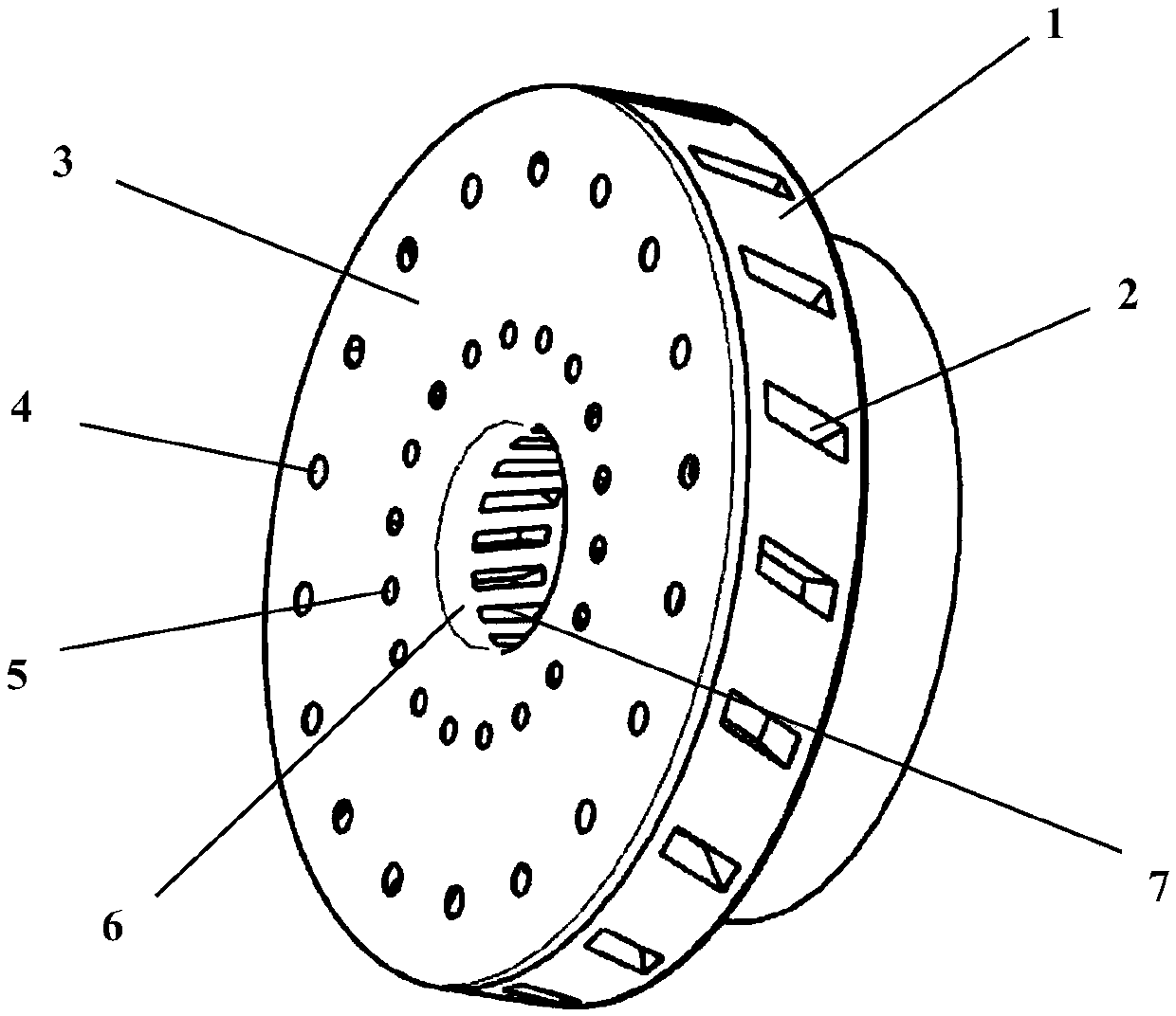
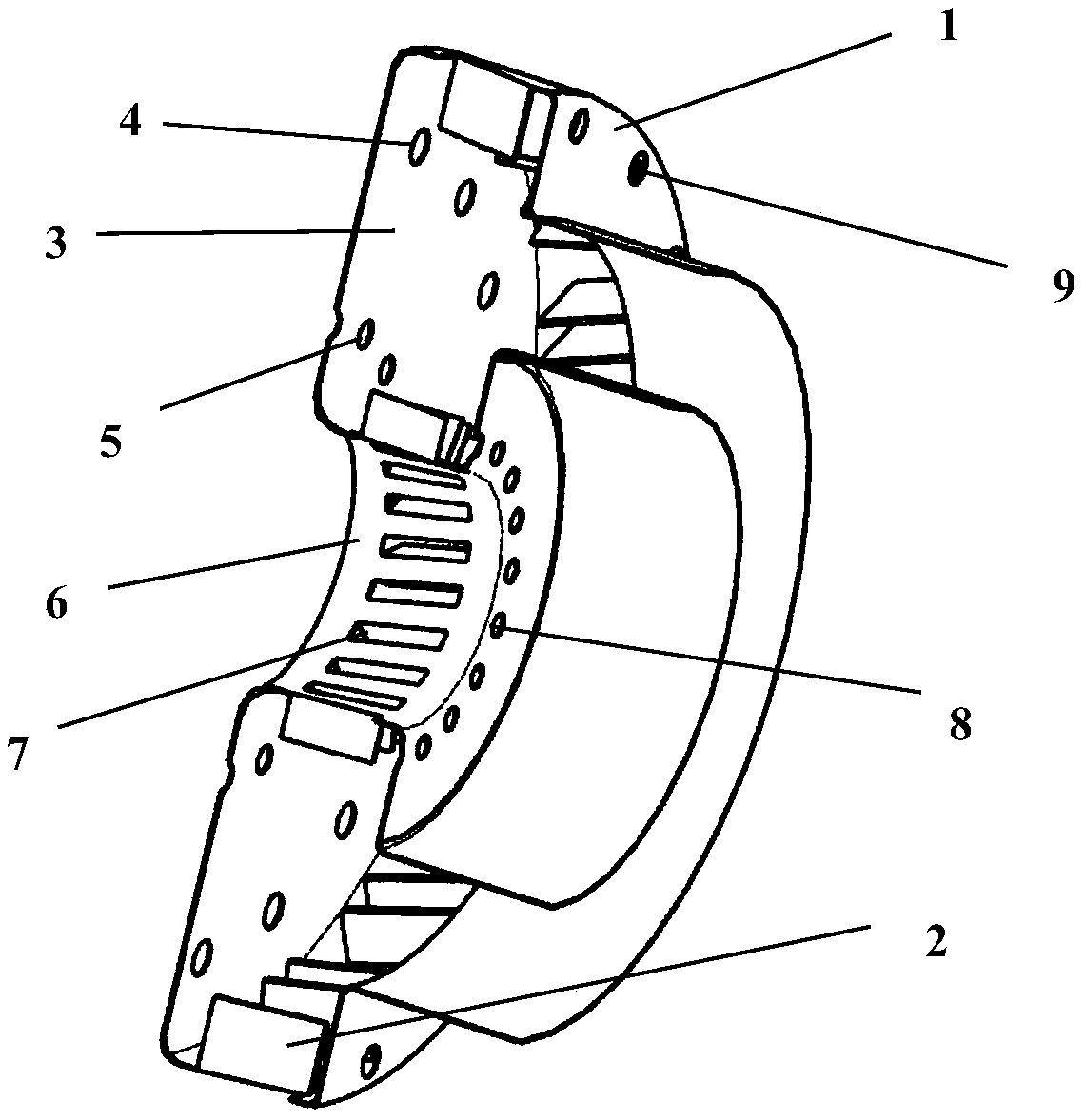
[0021] combine figure 1 , figure 2 , The invention provides a structure design of the combustion chamber of the swirling flow trapped vortex micro gas turbine engine that can effectively improve the combustion stability. figure 1 It is a structural schematic diagram of a swirl trapped vortex micro gas turbine engine combustor, figure 2 It is a cross-sectional schematic diagram of a swirl trapped vortex micro gas turbine engine combustor.

[0022] Such as figure 2 The air flow shown passes through 4-outer jet hole on the front wall, 5-inner jet hole on the front wall, 8-jet hole on the inner wall, 9-jet hole on the outer wall, 2-radial cyclone on the outer wall, 7-radial swirl on the inner wall The swirler enters the combustion chamber. The airflow entered by the jet hole outside the 4-front wall and the jet hole 9-the outer wall forms a stable axial recirculation zone...


PUM


Abstract

The present invention solves the technical problem that a swirl trapped vortex type combustion chamber of micro-turbine engine is provided. A main combustion region of the head of the flame tube adopts the form of a trapped vortex, which is a protruding structure, and the position and size of the jet holes are reasonably arranged. In addition, a radial swirler is disposed on the inner and outer walls of the micro-combustor flame tube. The airflow action of the jet holes is stable between blades of the radial swirler and has a certain strength axial backflow region, so that the residence time of the head airflow in the head region of the flame barrel is increased, and the combustion time of the fuel oil in the head region is increased. Besides, in addition to the axial backflow region generated by the jet holes, the radial swirler generates a circumferential backflow region in the head region, so that heat and mass exchange of each axial backflow interval can be carried out, and the ignition reliability and stability of the combustion chamber are improved. The high-temperature region of the combustion chamber is close to the head region, the temperature distribution uniformity of the outlet of the combustion chamber is good, and the overall combustion chamber performance of the combustion chamber is greatly improved.

Description

technical field [0001] The invention belongs to the field of micro gas turbine engine combustors, in particular to a swirl vortex micro gas turbine engine combustor. Background technique [0002] In recent years, micro-power systems have become a research hotspot at home and abroad, and micro-engines have become one of the most promising power devices because of their advantages such as small size, light weight, large output energy, and high density. The United States is the first country in the world to carry out research on small and micro turbine engine technology, and it is also the country with the most types and the most advanced technologies. In 1960, Williams International Corporation of the United States developed the world's first miniature turbojet engine WR2-1 with a thrust of 265N. Outside of the United States, Japan is also developing a micro-turbine engine with a power of 100W; China Taiwan, Nanjing University of Aeronautics and Astronautics, Beijing Universi...

Claims


Application Information

Patent Timeline
Patent Type & Authority Applications(China)
IPC IPC(8): F23R3/58
Inventor 张群寇睿张鹏王鑫海涵宋亚恒李承钰
Owner NORTHWESTERN POLYTECHNICAL UNIV
Learn More