Diagonal bracing structure for formwork
A diagonal brace and formwork technology, applied in the field of formwork diagonal brace structure, can solve the problems of formwork structure damage, time-consuming connection, inconvenient adjustment of diagonal braces, etc., and achieve the effect of convenient connection and disassembly, easy adjustment, and stable support structure
- Summary
- Abstract
- Description
- Claims
- Application Information
AI Technical Summary
Problems solved by technology
Method used
Image
Examples
Embodiment 1
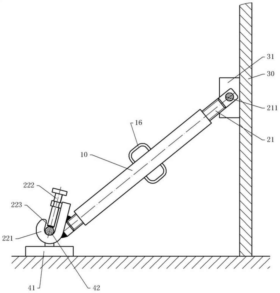
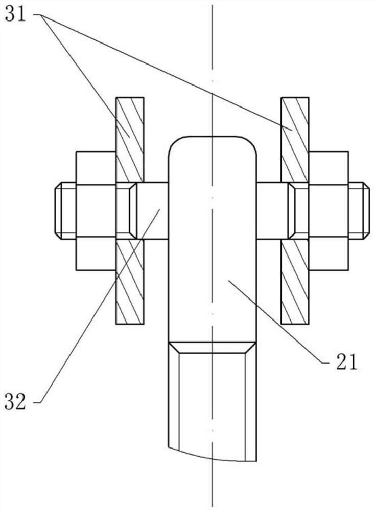
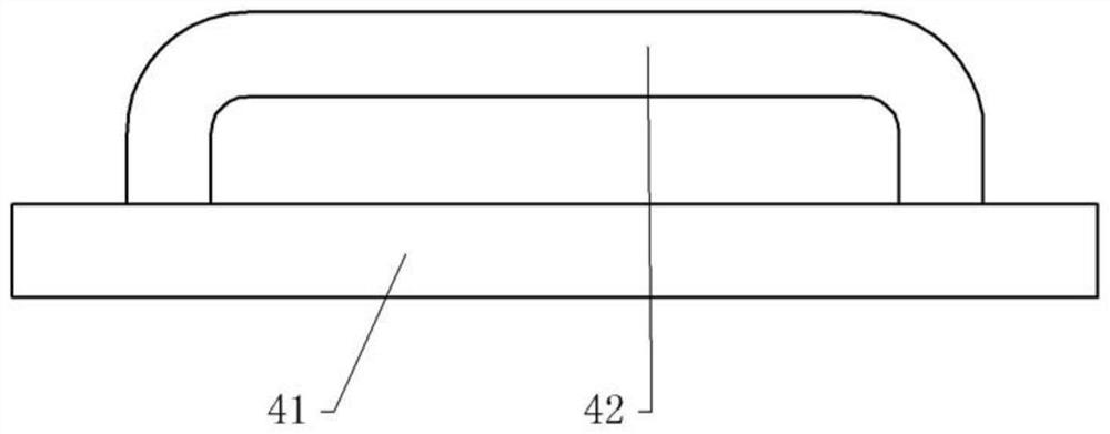
[0040] Such as figure 1 As shown, the formwork diagonal bracing structure of this embodiment includes a diagonal bracing connecting portion, a diagonal bracing rod and ground anchors fixed on the ground. Wherein, the diagonal brace includes a threaded sleeve 10 , an upper screw 21 and a lower screw 22 . One end of the upper screw 21 is inserted into the first sleeve 11 and threadedly connected with the first sleeve 11 , and the other end of the upper screw 21 is provided with a connection hole 211 for connecting the aluminum template 30 . One end of the lower screw rod 22 is inserted into the second sleeve 12 and is threadedly connected with the second sleeve 12, and the thread direction of the upper screw rod 21 and the lower screw rod 22 is opposite; the other end of the lower screw rod 22 is welded with a lock hook 221, the lock hook The opening of 221 faces the side of the screw 15 , and the groove 223 of the lock hook 221 forms an included angle of 30° with the lower scr...
Embodiment 2
[0045] Such as Figure 4 As shown, the difference between Embodiment 2 and Embodiment 1 is that in Embodiment 2, the two ribs 31 welded on the aluminum template 30 form an angle of 80°, and the tops of the two ribs 31 are welded against each other, so that The installation space formed between the two ribs 31 has only two open sides, one of which is the bottom of the installation space. Thus when the upper screw 21 and the aluminum formwork 30 form a hinged relationship, the upper parts of the two ribs 31 will cover the connection between the pin 32 and the upper screw 21, thereby preventing concrete from falling into the installation space and the end of the upper screw 21 and the upper screw 21 will be blocked. The pin 32 is covered so that it is inconvenient to disassemble the upper screw 21 and the pin 32 after the concrete is solidified.
Embodiment 3
[0047] Such as Figure 5 As shown, the difference between the third embodiment and the second embodiment is that a connecting piece 23 is provided in the installation space; the pin 32 passes through one end of the connecting piece 23 to form a rotational connection with the connecting piece 23 . The other end of the connector 23 is provided with an insertion hole, and the opening of the insertion hole is provided at the end of the connector 23 . The connecting piece 23 is provided with a sliding hole that runs through the connecting piece 23, and the sliding hole passes through the socket and is divided into two sections by the socket; wedges 231 are provided in the two sliding holes, and the wedges 231 can slide in the speaking hole. One end of the wedge 231 extends into the insertion hole, and the other end of the wedge 231 is provided with a pull ring 233 and is located outside the connecting member 23 . Both the sidewall of the sliding hole and the outer periphery of the...
PUM
 Abstract
Description
Claims
Application Information
 - R&D
- Intellectual Property
- Life Sciences
- Materials
- Tech Scout
- Unparalleled Data Quality
- Higher Quality Content
- 60% Fewer Hallucinations
Browse by: Latest US Patents, China's latest patents, Technical Efficacy Thesaurus, Application Domain, Technology Topic, Popular Technical Reports.
© 2025 PatSnap. All rights reserved.Legal|Privacy policy|Modern Slavery Act Transparency Statement|Sitemap|About US| Contact US: help@patsnap.com


