A filter device for reducing liquid rocket motor liquid flow test excess

A liquid rocket and filter device technology, applied in filtration and separation, fixed filter element filters, separation methods, etc., can solve problems such as affecting the validity of test data, affecting product reliability, inability to seal the pool, etc., to prevent impurities from entering the product. Internal, enhanced fluid stability, easy installation effect

Active Publication Date: 2020-12-18
BEIJING AEROSPACE PROPULSION INST
View PDF12 Cites 0 Cited by
  • Summary
  • Abstract
  • Description
  • Claims
  • Application Information

AI Technical Summary

Problems solved by technology

The whole test system involves many components, and the pool cannot be sealed during the test and calibration, which is more easily affected by the environment of the test bench, so the medium water contains impurities such as dust and rust residue
[0004] 2. Existing problems: Although there is a conventional system filter designed at the outlet connection product of the liquid flow test system, for the increasing number of research test products, its performance parameters can no longer meet the product requirements, and replacing the system filter will cause As a result, many routine tests cannot be carried out normally; at the same time, because there is a connecting hose between the system filter and the product, the hose may also produce redundant substances, so a special filter device needs to be designed and configured for a certain type of product with high requirements for the prevention of redundant substances ;In addition, under different flow rates and flow conditions, soft impurities such as fine fibers, although the filtration accuracy of the system is greater than the task requirements, some impurities are still left in the product through the system filter, which not only affects the validity of the test data, And directly affect the reliability of the product

Method used


Image

  • A filter device for reducing liquid rocket motor liquid flow test excess
  • A filter device for reducing liquid rocket motor liquid flow test excess

Examples


Embodiment Construction

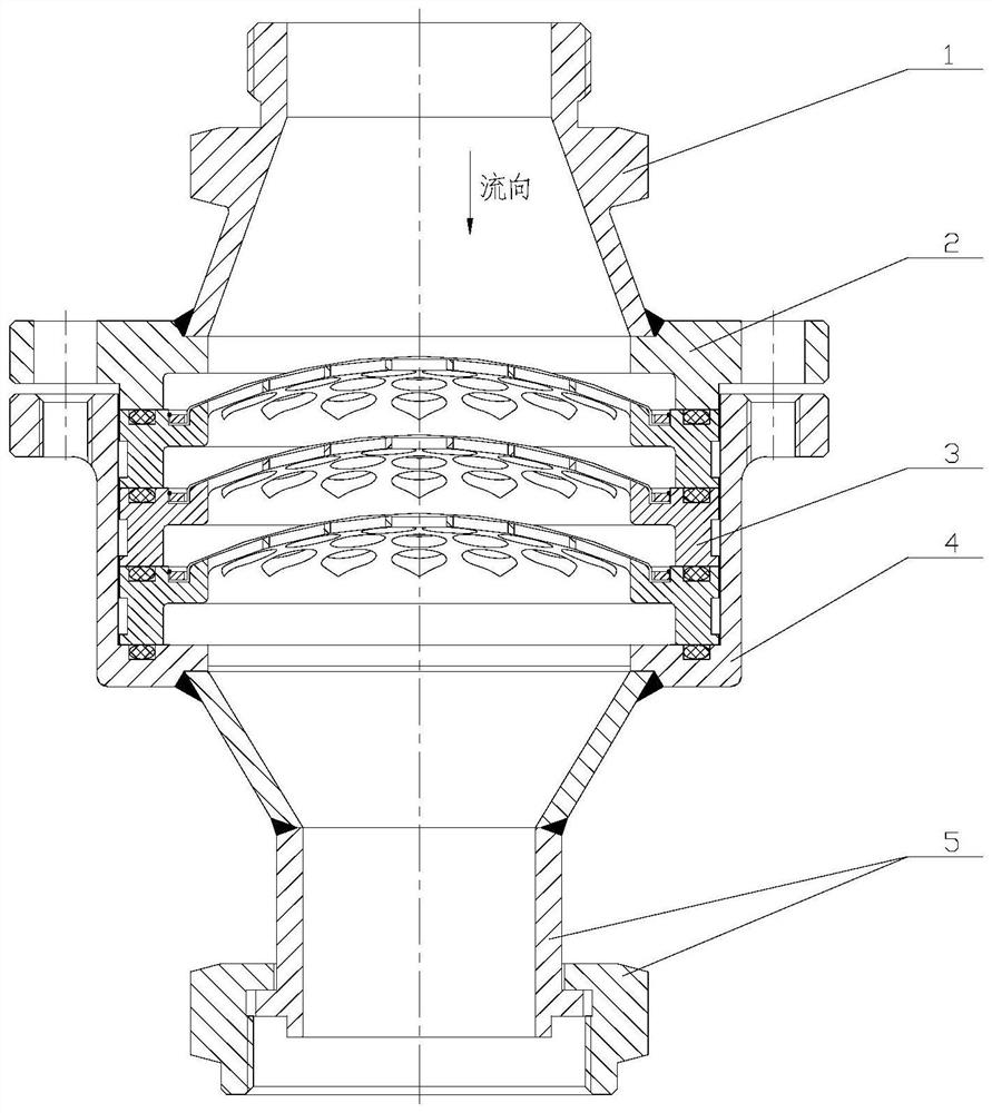
[0023] The invention proposes a filter device for reducing the excess in liquid rocket engine high pressure (pressure up to 5-6MPa) high flow rate (inlet flow rate is 10m / s) liquid flow test.

[0024] Such as figure 1 As shown, the present invention includes a first pipeline end 1 , an end cover 2 , a filter assembly 3 , a housing 4 and a second pipeline end 5 .

[0025] One end of the first pipeline end 1 is connected to the outlet of the system filter, and the other end is sealed to the end cover 2; one end of the second pipeline end 5 is connected to the product, and the other end is sealed to the housing 4, and the filter assembly 3 is installed on In the housing 4, the end cover 2 and the housing 4 are connected by fasteners, and the end cover 2 compresses the filter assembly 3; between the filter assembly 3 and the end cover 2, and between the filter assembly 3 and the housing 4 are sealed The ring is sealed.

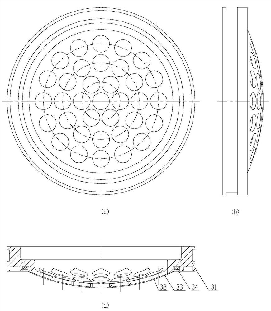
[0026] The filter assembly 3 is used to filter the tiny ex...


PUM

PropertyMeasurementUnit
diameteraaaaaaaaaa
diameteraaaaaaaaaa

Abstract

The invention relates to a filtration apparatus for reducing redundant materials of a liquid rocket motor liquid flow test. The filtration apparatus comprises a first pipeline end head, an end cap, afiltering assembly, a shell and a second pipeline end head, wherein one end of the first pipeline end head is connected to the outlet of a system filter, the other end of the first pipeline end head is sealedly connected to the end cover, one end of the second pipeline end head is connected to a product, the other end of the second pipeline end head is sealedly connected to the shell, the filtering assembly is arranged inside the shell, the end cover is connected to the shell through a fastener, the end cover presses the filtering assembly, and the filtering assembly is used for filtering micro redundant materials un-filtered by the system filter. According to the present invention, the filtration apparatus is arranged between the high-pressure high-flow-rate liquid flow test system filterand the product, can perform multiple filtrations on the micro redundant materials un-filtered by the system filter, and can ensure the validity of the test data and the reliability of the product.

Description

technical field [0001] The invention relates to a filtering device for reducing the redundant objects in the liquid flow test of a liquid rocket engine, and belongs to the field of prevention and control of the redundant objects in the liquid flow test of the parts and components of the liquid rocket engine. Background technique [0002] Liquid rocket engine technology is an experimental technology. Every component on the engine must pass strict ground test assessments to fully verify its working performance and reliability, and ensure that it is safe before participating in flight tests or launch missions. Therefore, testing is the basis for the development and batch production of liquid rocket engines, and the liquid flow test bench is just one of the test methods to verify whether the engine components meet the requirements. [0003] 1. Introduction of the liquid flow test bench: The liquid rocket engine liquid flow test bench mainly tests the relationship between the thr...

Claims


Application Information

Patent Timeline
Patent Type & Authority Patents(China)
IPC IPC(8): B01D29/56B01D29/05B01D29/96
CPCB01D29/05B01D29/56B01D29/96
Inventor 周琰黄萍黄文莉宋戈谷宇刘国龙彭宏
Owner BEIJING AEROSPACE PROPULSION INST
Why Eureka
Try Eureka