Column transport manipulator
A manipulator and cylinder technology, applied in the field of cylindrical transfer manipulators, can solve the problems of high labor intensity and low work efficiency, and achieve the effects of reducing manpower, improving efficiency, and holding workpieces smoothly.
- Summary
- Abstract
- Description
- Claims
- Application Information
AI Technical Summary
Problems solved by technology
Method used
Image
Examples
Embodiment 1
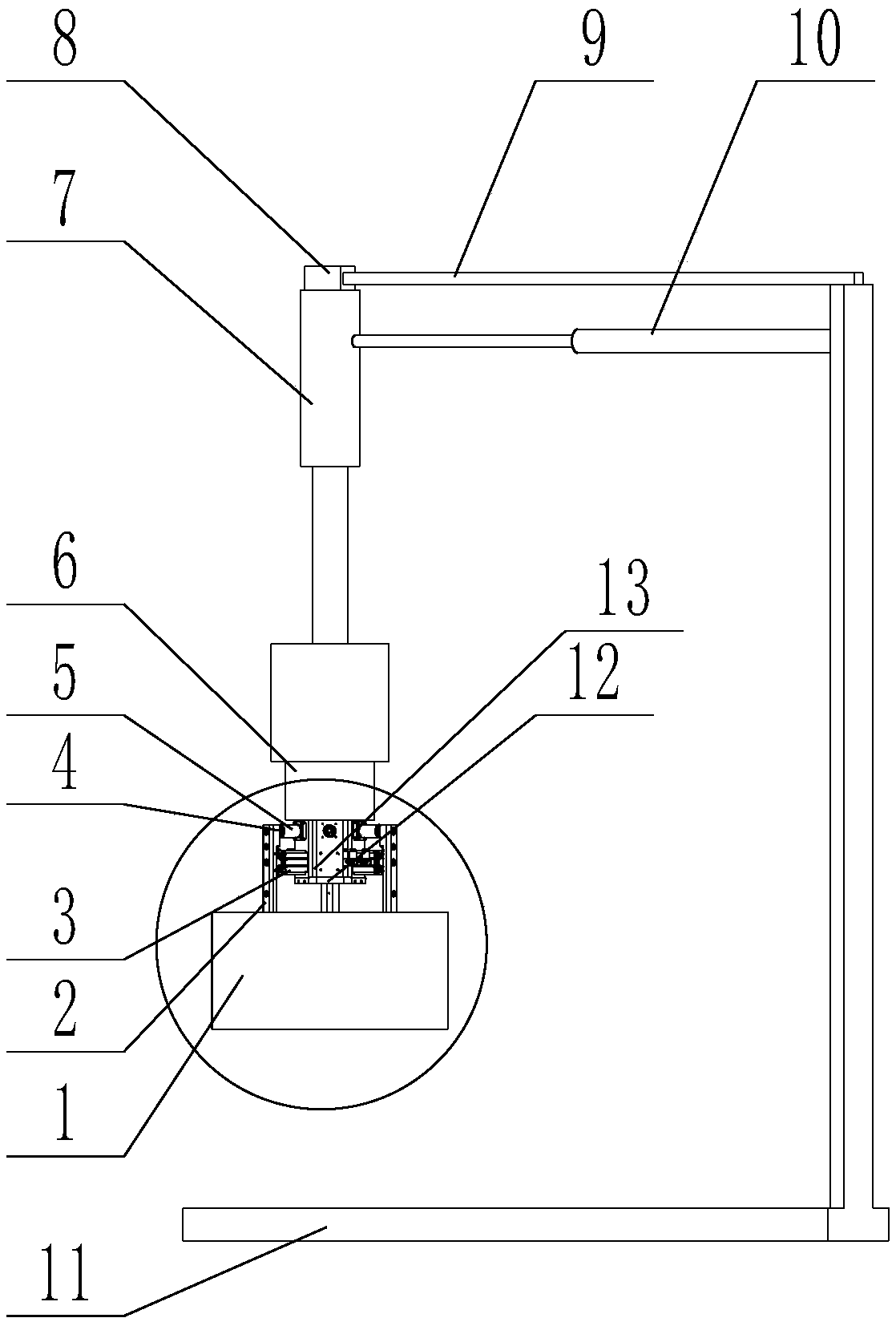
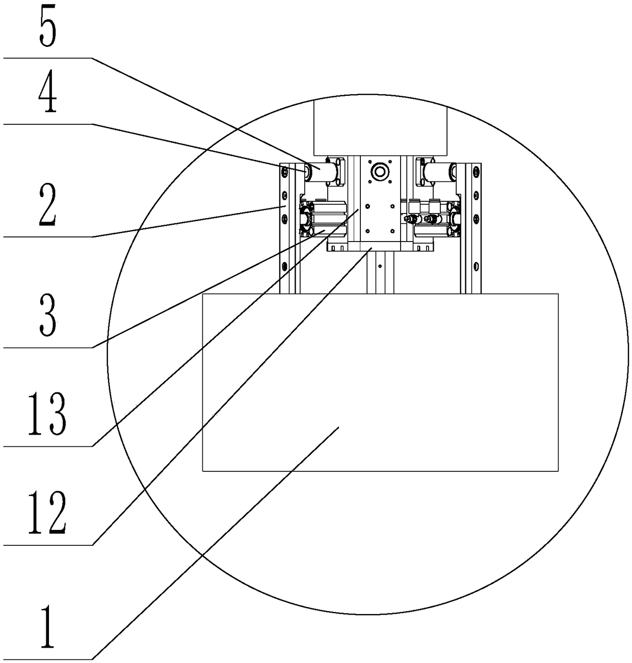
[0019] Such as Figure 1 to Figure 3 As shown, the present embodiment provides a cylindrical transfer manipulator, including a base 6, which is characterized in that three sets of positioning blocks 13 are evenly arranged under the base 6, and the positioning blocks 13 are fixed on the disc 12, and the positioning Blocks 13 are provided with thin cylinders 3, the thin cylinders 3 are connected with chucks 2, the workpiece 1 is connected below the chucks 2, the sides of the chucks 2 are rounded, and the positioning block 13 A flanged linear bearing 5 is arranged between the chuck 2 , and a precision guide shaft 4 runs through the middle of the linear bearing 5 .
[0020] In this embodiment, a base is included, and three sets of positioning blocks are evenly arranged under the base, and the positioning blocks are fixed on the disc, and thin air cylinders are arranged on the positioning blocks, and the thin air cylinders are connected with chucks. The sides of the chucks have ro...
Embodiment 2
[0022] This implementation case is a further improvement on Embodiment 1, specifically:
[0023] A first cylinder 7 is arranged above the base, and the cylinder body of the first cylinder 7 is fixed on a slider 8, and the slider 8 is sleeved on a cross bar 9, and the cross bar 9 is vertically fixed on an L-shaped on bracket 11.
[0024] A second cylinder 10 is arranged between the cylinder body of the first cylinder 7 and the L-shaped bracket 11 .
[0025] In this implementation case, by setting the first cylinder above the base, the base can be raised and lowered to realize the grabbing function. The first cylinder is fixed on the slider, and the slider is sleeved on the cross bar. The rod slides freely, and then the manipulator slides to realize the grabbing of different areas. By setting the second cylinder between the cylinder body of the first cylinder and the L-shaped bracket, the workpieces in different areas can be grasped through the second cylinder. Take, enhance t...
PUM
 Abstract
Description
Claims
Application Information
 - R&D
- Intellectual Property
- Life Sciences
- Materials
- Tech Scout
- Unparalleled Data Quality
- Higher Quality Content
- 60% Fewer Hallucinations
Browse by: Latest US Patents, China's latest patents, Technical Efficacy Thesaurus, Application Domain, Technology Topic, Popular Technical Reports.
© 2025 PatSnap. All rights reserved.Legal|Privacy policy|Modern Slavery Act Transparency Statement|Sitemap|About US| Contact US: help@patsnap.com


