
Air nailer

A nail gun and chamber technology, applied in the field of nail guns, can solve the problems of insufficient impact force of the nail gun, unfavorable miniaturization of the nail gun, poor nail driving effect, etc., and achieve good nail driving effect

Inactive Publication Date: 2018-10-16
NANJING CHERVON IND
View PDF5 Cites 4 Cited by
  • Summary
  • Abstract
  • Description
  • Claims
  • Application Information

AI Technical Summary

Problems solved by technology

On the one hand, in order to make the piston obtain a larger impulse during the impact process, the existing impact mechanism usually needs to increase the stroke of the piston movement, thereby increasing the volume of the cylinder, which is not conducive to the miniaturization of the nail gun; on the other hand, in order to Reducing the cylinder to reduce the size of the nail gun usually reduces the stroke of the piston movement, which in turn makes the impact force of the nail gun insufficient and the nailing effect is poor

Method used


Image

  • Air nailer
  • Air nailer
  • Air nailer

Examples


Embodiment Construction

[0023] figure 1 The illustrated nail gun 100 is used to generate an impact force on a nail so that the impact nail is driven into a workpiece.

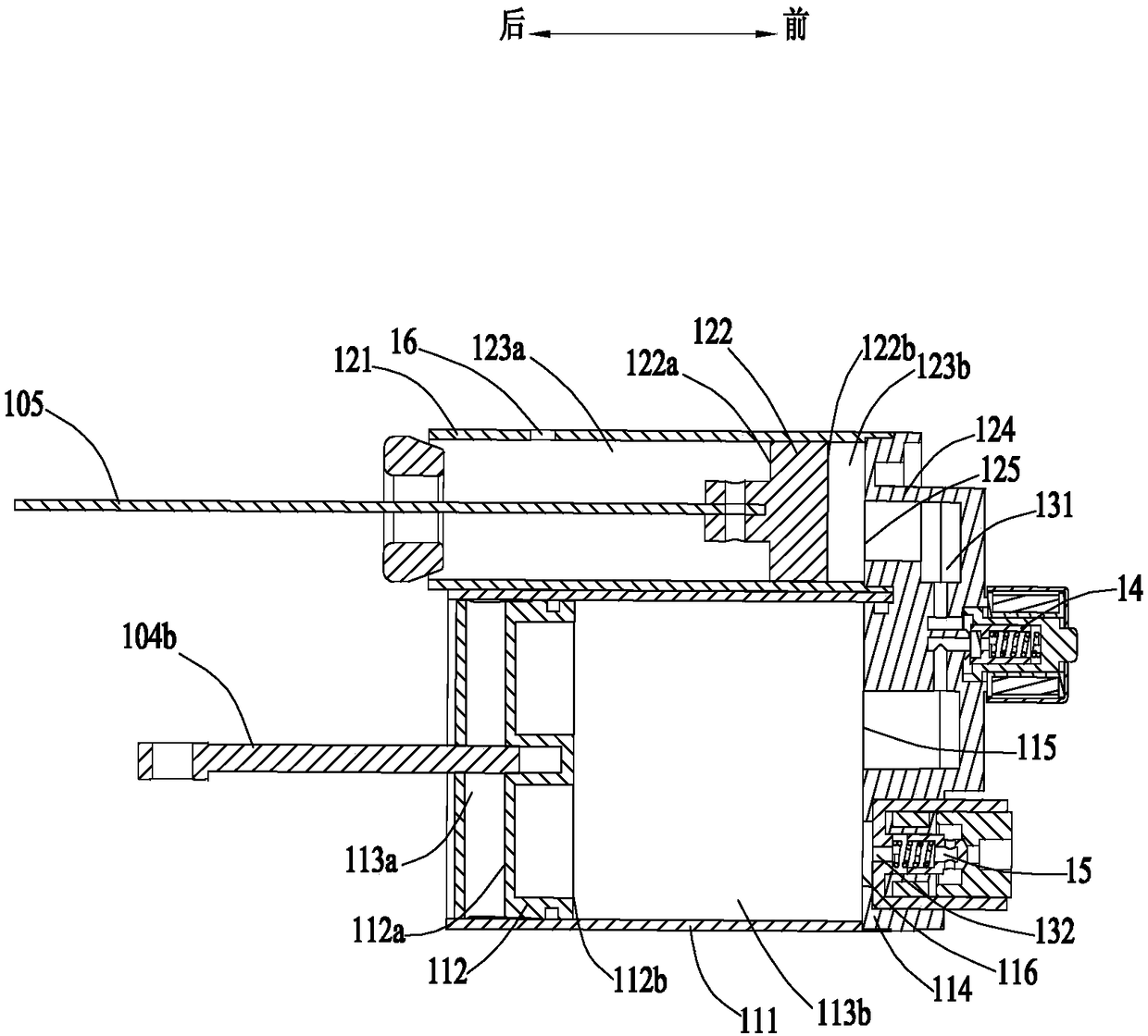
[0024] Such as figure 1 and figure 2 As shown, the nail gun 100 includes: a housing 101, a prime mover 102, an energy source 103, a driving device 104, an impact device 10, a striker 105, a locking device 106 and a nail box 107, wherein the impact device 10 includes: a first cylinder 11 And the second cylinder 12, the nail box 107 is used to accommodate nails.

[0025] The casing 101 is used to accommodate the prime mover 102 , the driving device 104 , the impact device 10 , etc., and the outside of the casing 101 is connected to a nail box 107 . Specifically, the housing 101 is formed with a handle portion 101a, a first accommodating portion 101b and a second accommodating portion 101c, wherein the first accommodating portion 101b is used for accommodating the impact device 10, and the second accommodating portion 101c is used fo...


PUM


Abstract

The invention discloses an air nailer, comprising a first cylinder, a second cylinder, a striker and a driving device, wherein the first cylinder comprises a first cylinder wall with a formed first chamber and a first piston; the second cylinder comprises a second cylinder wall with a formed second chamber and a second piston; the driving device comprises a driving member for driving the first piston; the first piston comprises a first surface connected with the driving member and a second surface; the second piston comprises a third surface connected with the striker and a fourth surface; thefirst chamber is divided by the first piston into a first chamber portion located on the side, where the first surface is arranged, of the first piston, and a second chamber portion located on the other side of the first piston; and the second chamber is divided by the second piston into a third chamber portion on the side, where the third surface is arranged, of the second piston, and a fourth chamber portion located on the other side of the second piston. The air nailer is further provided with a first air flow passage allowing the second chamber portion to communicate with the fourth chamber portion, and a second air flow passage allowing the first chamber portion to communicate with the third chamber portion. The air nailer provided by the invention has good nailing effect.

Description

technical field [0001] The invention relates to an electric tool, in particular to a nail gun. Background technique [0002] As a power tool, a nail gun can generate an impact force acting on a nail, so that the impact nail is driven into a workpiece. [0003] A nail gun usually includes: a housing, a cylinder, a piston, a firing pin, a prime mover, and an impact mechanism. On the one hand, in order to make the piston obtain a larger impulse during the impact process, the existing impact mechanism usually needs to increase the stroke of the piston movement, thereby increasing the volume of the cylinder, which is not conducive to the miniaturization of the nail gun; on the other hand, in order to Reducing the cylinder to reduce the size of the nail gun usually reduces the stroke of the piston movement, which in turn makes the impact force of the nail gun insufficient and the nailing effect is poor. Contents of the invention [0004] In order to solve the deficiencies of t...

Claims


Application Information

Patent Timeline
Patent Type & Authority Applications(China)
IPC IPC(8): B25C1/06
CPCB25C1/06
Inventor 吹拔正敏柯洪涛郝敬冬
Owner NANJING CHERVON IND
Learn More