Vibration sand discharging device for 3D printing and vibration sand spreading debugging method thereof

A 3D printing and sand laying technology, which is applied to casting molding equipment, casting molds, cores, etc., can solve the problems of increasing product rejection rate, different sanding amount, and insufficient sanding amount, so as to avoid sand leakage and control flexibly Effect

Pending Publication Date: 2018-10-16
NINGXIA KOCEL MOLD
View PDF11 Cites 6 Cited by
  • Summary
  • Abstract
  • Description
  • Claims
  • Application Information

AI Technical Summary

Problems solved by technology

However, in the current sanding process, there are often insufficient sand in some areas or sand leakage in non-sanding areas. Analysis of the reasons is mainly caused by two aspects. One is that the vibration transmitted by the vibration motor to each part is uneven. As a result, the amount of sand is different; the second is that there is no throttling device at the sand outlet to cause sand leakage; moreover, mechanical vibration has defects such as bearing wear and vibration volume cannot be adjusted. When problems occur, they cannot be solved immediately. , which leads to the scrapping of printed products and increases the reject rate of products

Method used


Image

  • Vibration sand discharging device for 3D printing and vibration sand spreading debugging method thereof
  • Vibration sand discharging device for 3D printing and vibration sand spreading debugging method thereof
  • Vibration sand discharging device for 3D printing and vibration sand spreading debugging method thereof

Examples


Embodiment 1

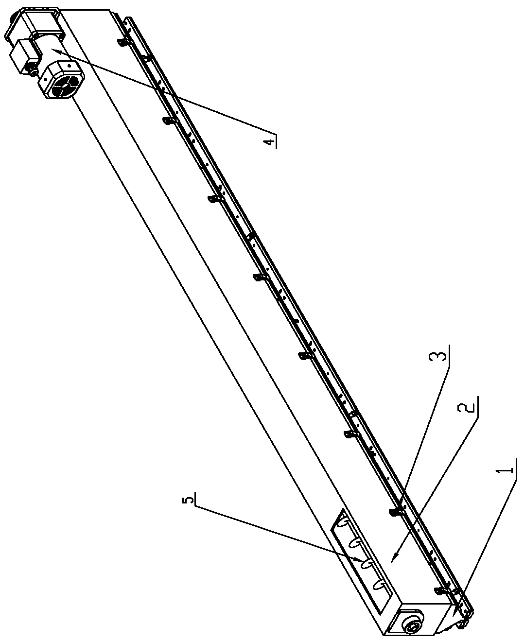
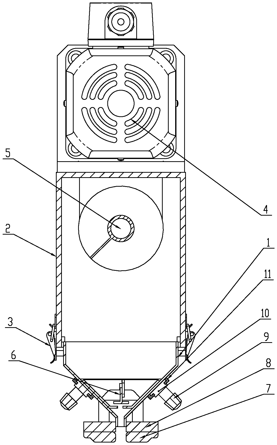
[0031] Such as figure 1 — Image 6 Shown is the vibrating sand lowering device for 3D printing of the present invention, which includes a sand bucket 1, a sand bin 2 is arranged above the sand bin 1, a spiral agitator 5 is arranged inside the sand bin 2, and an agitator motor is arranged at the top end of the sand bin 2 4. The other end of the top of the sand bin 2 is provided with a sand supply port, and the bottom of the sand bucket 1 is provided with a sand outlet with a fixed width along the length direction. The sand bucket 1 above the mouth is provided with a self-stopping sand device 6, and the two outer walls of the sand bucket 1 along the length direction are respectively symmetrically provided with slide rails 11, and several slide blocks 10 are respectively arranged on the slide rails 11. 10 is connected with a vibration cylinder 9, and the bottom of the sand outlet is connected with a sand scraper 7 through a sand scraper bracket 8 fixed on the outer wall of the s...

Embodiment 2

[0040] This embodiment is a debugging method for vibrating sand laying using the vibrating sand lowering device for the printer of the above embodiment, including the following steps:

[0041] 1) Determine the angle of repose α of the sanding powder;

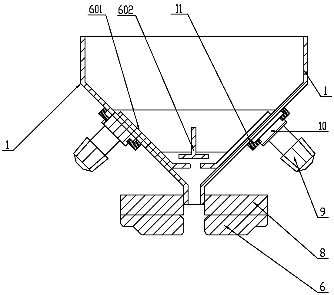
[0042] 2) Disassemble the sand bucket 1 from the bottom of the sand bin 2 to expose the T-shaped sand tank 601 and the internal adjustment plate 602, adjust the height of the adjustment plate 602 in the T-shaped sand tank 601, so that the adjustment plate 602 and the T-shaped sand tank The blanking accumulation angle formed by the bending part of 601 is the same as the angle of repose α in step 1), and the adjusting plate 602 is fixed in the T-shaped sand tank 601;

[0043] 1) Determine the angle of repose of the sand powder material and the width d of the sand falling joint;

[0044] 2) Disassemble the sand bucket 1 from the bottom of the sand bin 2 to open the internal structure. First, adjust the installation height of the i...


PUM


Abstract

The invention relates to the technical field of sand spreading devices for 3D printing, and relates to a vibration sand discharging device for a 3D printer and a vibration sand spreading debugging method thereof. The vibration sand discharging device for 3D printing comprises a sand hopper, and a sand bin is arranged above the sand hopper; a spiral stirring wheel is arranged in the sand bin, and the top of the sand bin is provided with a stirring wheel motor and a sand supply opening; a sand outlet with a fixed width is formed below the sand hopper in the length direction; the cross section, perpendicular to the length direction, of the sand hopper on the upper side of the sand outlet is in a V shape; a self-leakage-stopping sand discharging device is arranged in the sand hopper above thesand outlet, sliding rails are symmetrically arranged on the two outer walls of the outer side of the sand hopper in the length direction respectively, a plurality of sliding blocks are arranged on the sliding rails respectively, and a vibration air cylinder is connected to the sliding blocks; the lower side of the sand outlet is connected with a sand scraping plate. After the vibration air cylinder stops vibrating, the self-leakage-stopping sand discharging device stops sand flowing to the sand discharging opening. The sand discharging structure can be used for uniformly spreading sand in thelength direction when sand spreading is carried out, and self sand stopping can be effectively achieved after vibration is stopped.

Description

technical field [0001] The invention relates to the technical field of 3DP printing sanding devices, in particular to a vibrating sanding device for a 3D printer and a debugging method for vibrating sanding. Background technique [0002] In the sand mold 3D printing technology in the prior art, the sand used to print the sand mold needs to be mixed with a curing agent first, and in the printing process, it is combined with the resin ejected from the print head to form a sand mold with a certain strength. The printing process is briefly described as follows. Before sand and resin are mixed, the sand needs to be paved layer by layer. After finishing a layer of sand, the print head will move and sweep across the entire sand surface. When it moves to a specific position where resin needs to be sprayed, the print head will spray the resin at fixed points and quantitatively to mix with the sand mixed with curing agent, and then proceed to the next step. Sand one layer. However, ...

Claims


Application Information

Patent Timeline
Patent Type & Authority Applications(China)
IPC IPC(8): B22C9/02B33Y30/00
CPCB22C9/02B33Y30/00
Inventor 彭凡何捷军杨保
Owner NINGXIA KOCEL MOLD
Why Eureka
Try Eureka