
Tilting mirror vibration suppression method based on improved disturbance observer

A disturbance observer and vibration suppression technology, which is applied in the field of disturbance suppression ability of photoelectric tracking system and vibration suppression of tilting mirror, can solve the problems of small closed-loop bandwidth and affecting system performance, and achieve the goal of reducing impact, optimizing sensitivity function and saving cost Effect

Active Publication Date: 2018-10-12
INST OF OPTICS & ELECTRONICS - CHINESE ACAD OF SCI
View PDF10 Cites 3 Cited by
  • Summary
  • Abstract
  • Description
  • Claims
  • Application Information

AI Technical Summary

Problems solved by technology

[0003] Aiming at the problem that the vibration of the mechanical structure of the large telescope affects the system performance, and the closed-loop bandwidth of the image sensor is small under the long integration time, the present invention proposes an improved disturbance observer to improve this problem

Method used


Image

  • Tilting mirror vibration suppression method based on improved disturbance observer
  • Tilting mirror vibration suppression method based on improved disturbance observer
  • Tilting mirror vibration suppression method based on improved disturbance observer

Examples


Embodiment Construction

[0030] The specific implementation manners of the present invention will be described in detail below in conjunction with the accompanying drawings.

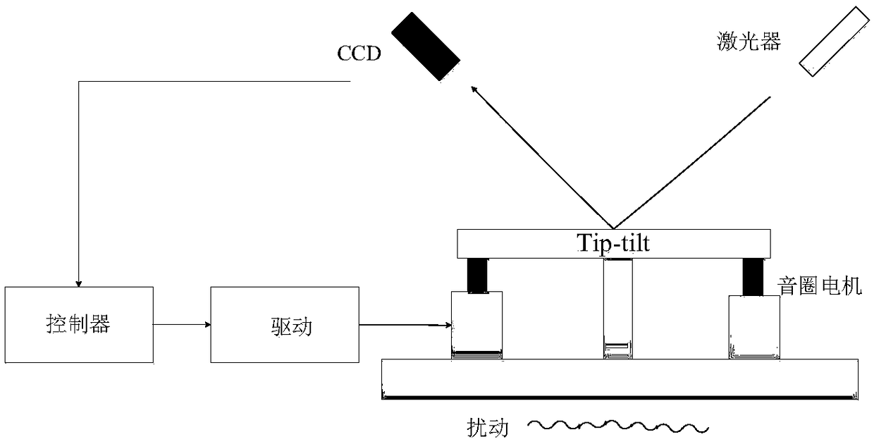
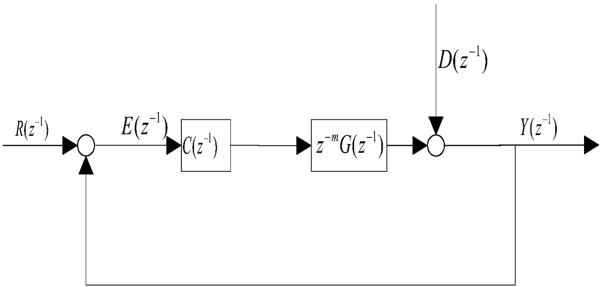
[0031] as attached image 3 Shown is a control block diagram of a tilting mirror vibration suppression method based on an improved disturbance observer, which includes a CCD (charge-coupled device) position loop and a disturbance observer. The specific implementation steps of using the device to improve system performance are as follows:

[0032] Step (1): Build a figure 1 The experimental platform under the classic feedback control loop is shown. The control system uses CCD as position feedback and target deviation detection feedback element to form a tracking loop;

[0033] Step (2): According to the attached figure 2 The classic control structure of the image sensor CCD is used to realize the position controller C(z -1 ) and position closed loop, thus realizing the basic position closed loop feedback control;

[0034] St...


PUM


Abstract

The invention discloses a tilting mirror vibration suppression method based on an improved disturbance observer. Since mechanical vibrations of an astronomical telescope make the closed-loop performance of a telescope control system decline and these vibrations cannot be well remedied by a classical control structure, the method adopts a tilting mirror to suppress the vibrations. According to themethod, by designing an improved Q filter., a sensitivity function of a tilting mirror control system is optimized, the large-amplitude vibrations are effectively suppressed, and the influence of a water bed effect on the system performance is reduced. Under the case that the system disturbance frequency is known, the control method can achieve optimal correction, and the disturbance suppression capability of the system is effectively improved. According to the method, the system is optimized from a control algorithm, only one image sensor is needed, and the cost is saved. At the same time, the method is clear, the structure is simple, there is no dependence on models, and the method is easy to operate and implement.

Description

technical field [0001] The invention belongs to the field of inertial stability control of a photoelectric tracking platform, and in particular relates to a method for suppressing vibration of a tilted mirror based on an improved disturbance observer, which is mainly used for improving the disturbance suppression capability of a photoelectric tracking system such as a large telescope system. Background technique [0002] Large telescopes promise to see fainter and more distant objects in deep space exploration. However, the observation performance of the telescope may be affected by the vibration caused by vehicles, air conditioners or wind during operation, especially the mechanical structure vibration of the telescope, which cannot be compensated by the classic control loop. For distant objects, a long exposure time can obtain a better signal-to-noise ratio, but the longer the exposure time of the image sensor, the smaller the bandwidth of the control loop. Furthermore, i...

Claims


Application Information

Patent Timeline
Patent Type & Authority Applications(China)
IPC IPC(8): G05B13/04
CPCG05B13/042
Inventor 牛帅旭唐涛亓波包启亮曹雷蒋晶赵志强杨涛
Owner INST OF OPTICS & ELECTRONICS - CHINESE ACAD OF SCI
Learn More