Abnormal-shaped groove seam cooling structure capable of improving end wall cooling efficiency

A cooling structure and cooling efficiency technology, applied in the cooling of the engine, the cooling of the turbine/propulsion device, engine components, etc., can solve the problems of insufficient cooling protection, uneven distribution of cooling jets, uneven flow distribution, etc., to achieve Safe and efficient operation, improved end wall cooling efficiency, universal applicability

Active Publication Date: 2018-10-12
XI AN JIAOTONG UNIV
View PDF5 Cites 3 Cited by
  • Summary
  • Abstract
  • Description
  • Claims
  • Application Information

AI Technical Summary

Problems solved by technology

The traditional slot cooling structure 8 and the air film hole 9 cooling structure can improve the cooling efficiency of the end wall near the leading edge of the vane to a certain extent. The distribution is uneven, so that the vane channel end wall 10 area near the leading edge of the vane and the pressure surface side still cannot receive sufficient cooling protection

Method used


Image

  • Abnormal-shaped groove seam cooling structure capable of improving end wall cooling efficiency
  • Abnormal-shaped groove seam cooling structure capable of improving end wall cooling efficiency
  • Abnormal-shaped groove seam cooling structure capable of improving end wall cooling efficiency

Examples


Embodiment Construction

[0032] The present invention will be further described in detail below in conjunction with the accompanying drawings and technical principles.

[0033] Concrete structure of the present invention sees appendix Figure 3-6, the design idea is as follows:

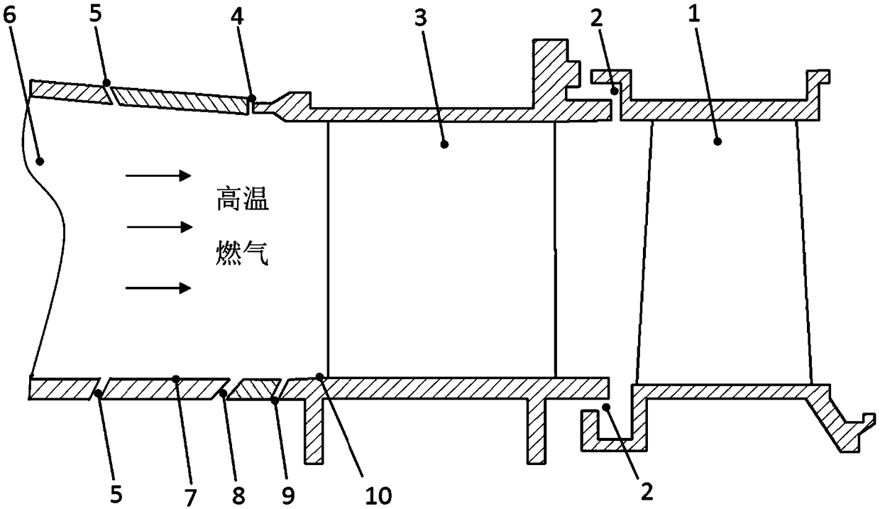
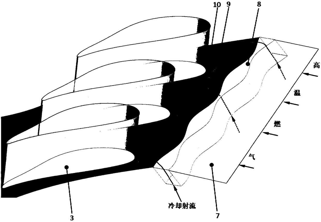
[0034] see image 3 with Figure 4 ,and figure 2 Compared with the traditional slot cooling structure, the actual gas turbine combustion chamber 6 and turbine stationary blade cascade 3 are processed and installed separately, so there is a slot cooling structure 8 between the combustion chamber 6 and the turbine stationary vane cascade 3 . In an actual gas turbine, the cooling air flow is introduced into the slot cooling structure 8 to cool the end wall 10 of the downstream vane channel. In the slot cooling structure 8 of the present invention, the slot cooling structure upstream boundary 13 and the slot cooling structure downstream boundary 15 of the slot outlet are designed to be cosine functions with opposite phases a...


PUM


Abstract

The invention discloses an abnormal-shaped groove seam cooling structure capable of improving stationary blade channel end wall cooling efficiency, a groove seam cooling structure upstream boundary and a groove seam cooling structure downstream boundary of a groove seam outlet of the groove seam cooling structure are in shapes of cosine functions with opposite phases and the same period and amplitude, and the periods and the stationary blade grid pitches of the cosine functions of the groove seam cooling structure upstream boundary and the groove seam cooling structure downstream boundary areequal. In the practical gas turbine working process, the outlet areas of the groove seam cooling structure are continuously changed according to a certain rule in the pitch direction, cooling jet flowintroduced through a gas compressor is redistributed when entering a jet flow groove so that uneven distribution of the cooling jet flow at the groove seam outlet due to pressure changes of the exterior flowing field can be overcome. By means of the groove seam cooling structure, the cooling jet flow is distributed more evenly at the groove seam outlet, the coverage area of the cooling jet flow at the downstream end wall is enlarged, and therefore the groove seat cooling jet flow can be tightly attached to the end wall to conduct sufficient cooling protection on the downstream stationary blade channel end walls.

Description

technical field [0001] The invention relates to an end wall slot cooling structure, in particular to a special-shaped slot cooling structure between a gas turbine combustion chamber and a turbine with improved end wall cooling efficiency. Background technique [0002] With the adjustment of the energy structure, gas turbines, as the main device for energy conversion and utilization, are widely used in civil power generation, aviation industry, chemical industry and mechanical power fields due to their high thermal power conversion efficiency. The rapid development of social economy has led to a sharp increase in energy demand and increasingly prominent environmental problems. As the main power generation equipment, the power and thermal efficiency of gas turbines have been continuously improved, and increasing the gas temperature is the most direct and effective way to increase the power and efficiency of gas turbines. However, this puts more stringent requirements on the co...

Claims


Application Information

Patent Timeline
Patent Type & Authority Applications(China)
IPC IPC(8): F02C7/12
CPCF02C7/12
Inventor 李军杜昆李志刚
Owner XI AN JIAOTONG UNIV
Why Eureka
Try Eureka