
Connecting mould plate for inside corner and outside corner and with adjustable angle

A technology of yin and yang corners and templates, which is applied to the preparation of formwork/formwork components and building components on site, construction, etc., can solve problems affecting the construction period, irregular shape, material waste, etc., and improve construction efficiency and turnover rate High, easy to disassemble and adjust

Pending Publication Date: 2018-10-12
CHINA THIRD METALLURGICAL GRP
View PDF6 Cites 3 Cited by
  • Summary
  • Abstract
  • Description
  • Claims
  • Application Information

AI Technical Summary

Problems solved by technology

[0003] With the rapid development of the construction industry, buildings are no longer limited to square structures, but are developing in the direction of personalization and the pursuit of modern design; in the actual construction process, buildings with irregular shapes are often encountered; Most of the traditional internal corner formwork and external corner formwork are fixed angles, and the most commonly used one is 90 degree angle. If you encounter a special angle, you need to customize it, which seriously affects the construction period; and when the usage is large, there is no need to repeat the customized formwork with fixed angles. Utilize value, resulting in material waste and cost increase

Method used


Image

  • Connecting mould plate for inside corner and outside corner and with adjustable angle
  • Connecting mould plate for inside corner and outside corner and with adjustable angle
  • Connecting mould plate for inside corner and outside corner and with adjustable angle

Examples


Embodiment Construction

[0021] The specific embodiment of the present invention will be further described below in conjunction with accompanying drawing:

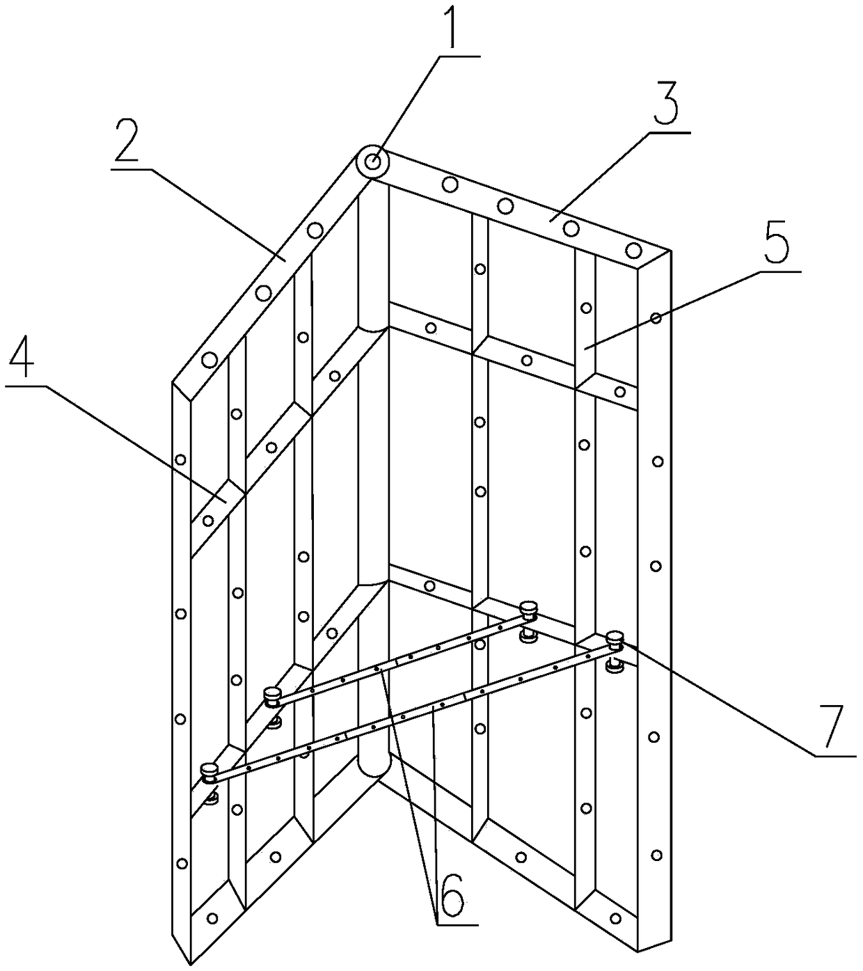
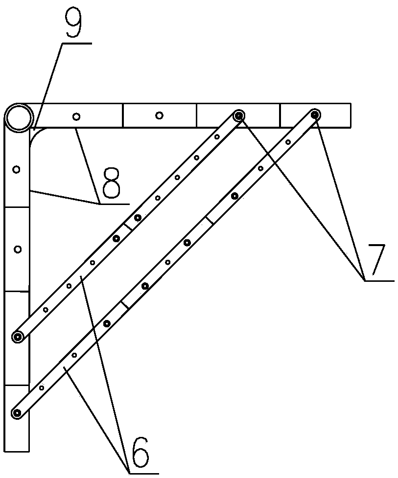
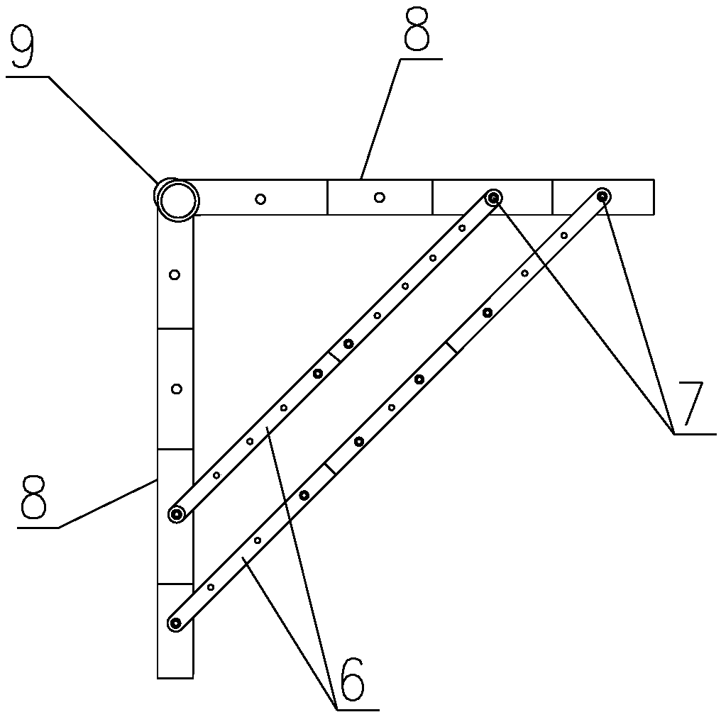
[0022] like figure 1 As shown in the present invention, an angle-adjustable dual-purpose connecting formwork for male and female angles includes a flat formwork A 2, a flat formwork B 3, an adjustable connector 6 and a shaped corner protector 9; the flat formwork A 2 and the flat formwork B 3 is composed of board surface, horizontal flute 4 with holes, and vertical flute 5 with holes. Multiple mold flute 4 with holes and vertical flute 5 with holes are intersected on one side of the board surface to form a grid structure. The other side is the working surface 8; one side of the flat template A 2 and one side of the flat template B 3 are hinged together through the connecting axis 1 to form a symmetrical structure centered on the connecting axis 1, and the working surface 8 is located at the same side; the non-working surface side of the flat form...


PUM


Abstract

The invention relates to a connecting mould plate for inside corner and outside corner and with adjustable angle. The connecting mould plate comprises a flat mould plate A, a flat mould plate B, adjustable connecting pieces and shaping and protecting corners. The flat mould plate A and the flat mould plate B are composed of plates, horizontal edges with holes, and longitudinal edges with holes; one lateral side of the flat mould plate A is hinged to one lateral side of the flat mould plate B by a connecting shaft to form a symmetrical structure with connecting shaft as center, and the workingfaces are on the same side; a plurality of adjustable connecting pieces are arranged on the non-working sides of the flat mould plate A and the flat mould plate B; two ends of the adjustable connecting pieces are detachably fixedly connected with the flat mould plate A and the flat mould plate B; the flat mould plate A and the flat mould plate B rotate around the connecting shaft, and the includedangle of the flat mould plate A and the flat mould plate B can be adjusted in a range from 5 degrees to 355 degrees; after the angle is adjusted, the flat mould plate A and the flat mould plate B arelocked and fixed by the adjustable connecting pieces; and smooth transition of connecting portions of the workpieces is achieved by the shaping and protecting corners. The structure is simple, use isflexible and convenient, the recycle rate is high, construction efficiency is improved and construction cost is lowered.

Description

technical field [0001] The invention relates to the technical field of cast-in-place concrete construction, in particular to an angle-adjustable dual-purpose connecting formwork for both male and female angles used for pouring formwork during cast-in-place concrete construction. Background technique [0002] In the construction of cast-in-place concrete, various formworks are required; among them, the combined formwork is a tool-type shaped formwork, which is composed of several types of plates, corner forms, supports and connectors with a certain modulus, and can be assembled flexibly and easily. Available in a variety of sizes and geometric shapes, with strong versatility, it is suitable for the construction needs of beams, columns, panels, walls, foundations and other components of various buildings. The commonly used combined shaped steel formwork is mainly composed of three parts: steel formwork, connectors and support parts, among which steel formwork includes four typ...

Claims


Application Information

Patent Timeline
IPC IPC(8): E04G9/02
CPCE04G9/02
Inventor 王恺
Owner CHINA THIRD METALLURGICAL GRP
Learn More