Tailoring device for garment processing

A cutting device and clothing technology, applied in the field of clothing processing, can solve the problems of cloth waste, etc., and achieve the effect of convenient use, simple structure, and convenient lateral movement

Inactive Publication Date: 2018-10-12
湖州吴兴华溢服装厂
View PDF1 Cites 3 Cited by
  • Summary
  • Abstract
  • Description
  • Claims
  • Application Information

AI Technical Summary

Problems solved by technology

[0002] In the process of garment processing, fabric cutting is an extremely important part. If there is a mistake in cutting, it will easily cause waste of fabric. For the disadvantages of traditional cutting in curve cutting and fine cutting, modern cutting has gradually become popular as laser cutting. After searching , the patent document whose authorized announcement number is CN107900532A discloses a cutting device for garment processing, slide rails are installed on both sides of the base, support columns are installed on the slide rails, and the two ends of the slide rails are connected to limit A rotating shaft is installed on the limit block, and a hydraulic telescopic rod is connected to the rotating shaft, and a tension sensor is connected to the hydraulic telescopic rod. The type of the tension sensor is EVT-10H, and the tension sensor A mounting block is connected to one end of the mounting block, an upper plate and a bottom plate are installed on the mounting block, electromagnets are installed in the upper plate and the bottom plate, a crossbeam is installed on the support column, and a slide rail is arranged in the crossbeam, The beam is connected to the laser through a slide rail, a laser head is installed at the bottom of the laser, a heat conduction ring is installed outside the laser head, and heat conduction strips are installed on both sides of the heat conduction ring. In the present invention, the cloth is stretched , in the process of cutting, it can keep the overall flatness of the fabric, reduce the error of cutting, and be more convenient to use, but this design still has shortcomings, and it is convenient to move the cutting equipment laterally, so we propose a garment processing The cutting device is used to solve the above problems

Method used


Image

  • Tailoring device for garment processing
  • Tailoring device for garment processing
  • Tailoring device for garment processing

Examples


Embodiment Construction

[0023] The following will clearly and completely describe the technical solutions in the embodiments of the present invention with reference to the accompanying drawings in the embodiments of the present invention. Obviously, the described embodiments are only some, not all, embodiments of the present invention.

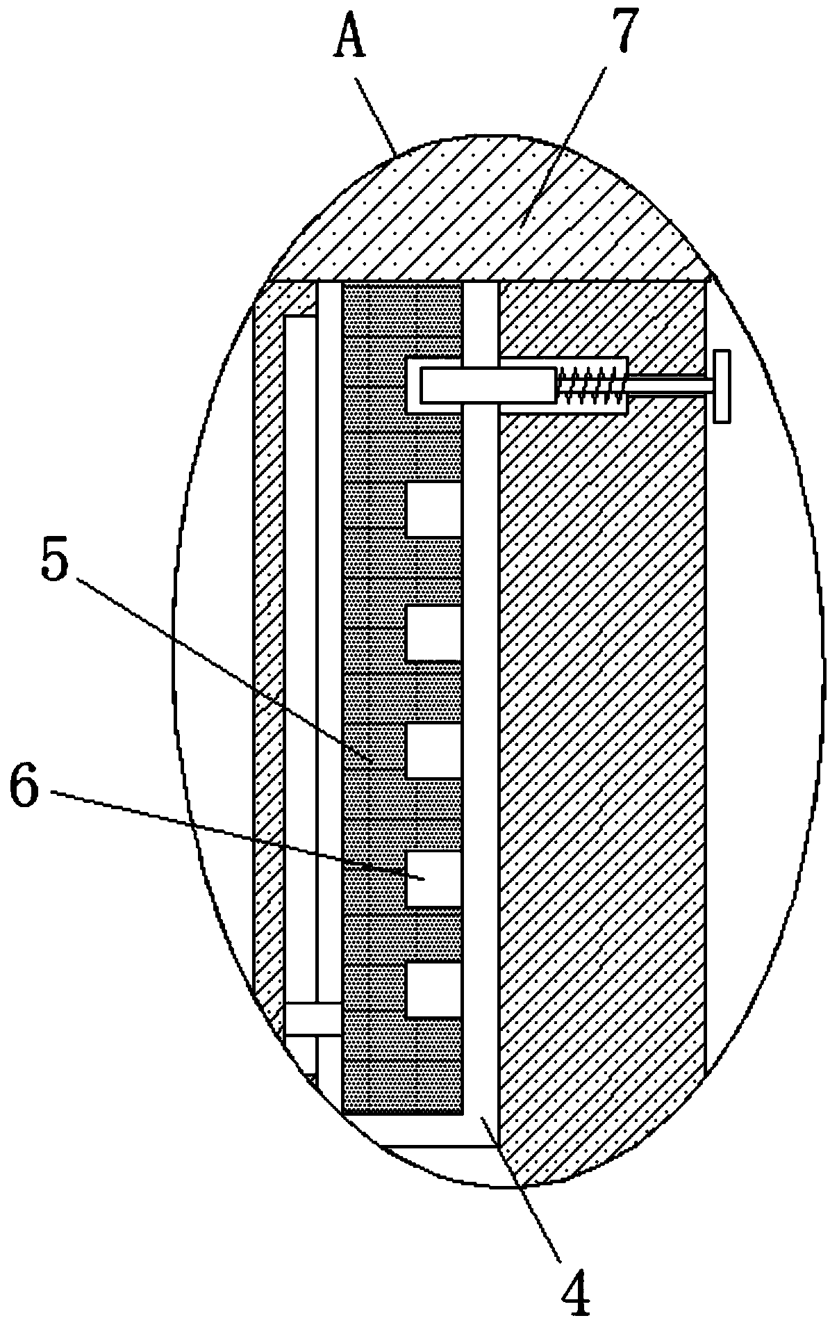
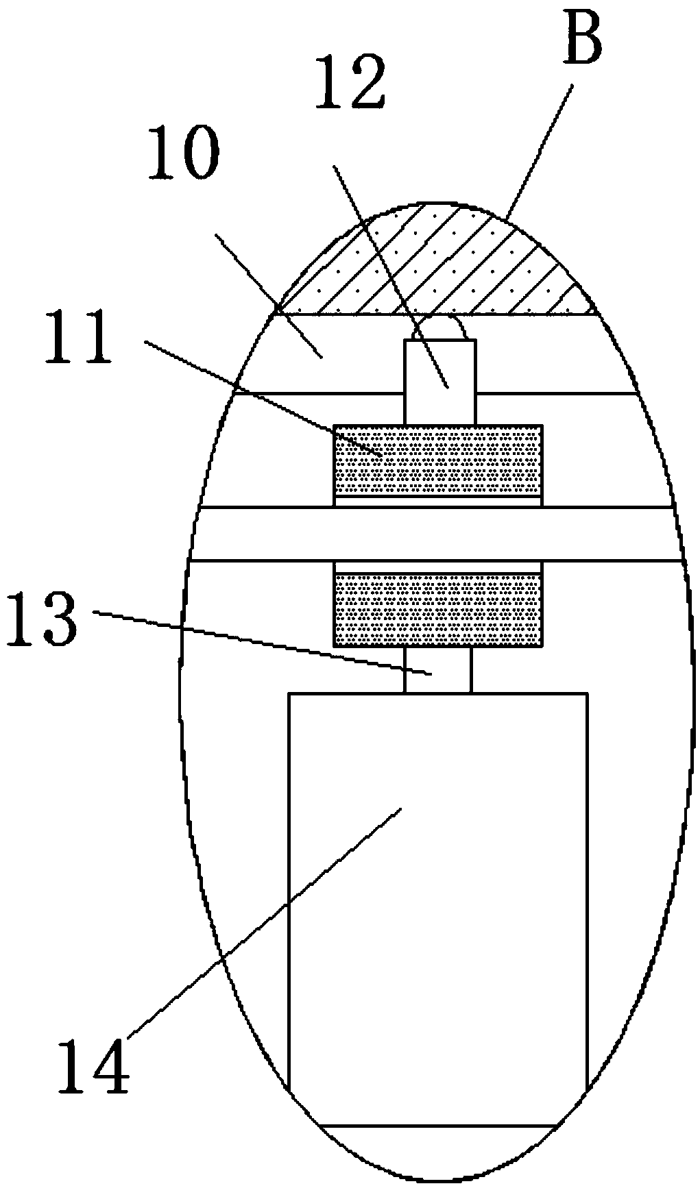
[0024] refer to Figure 1-3 , a cutting device for garment processing, comprising a workbench 1, a base 2 is fixedly installed on both sides of the workbench 1, a support column 3 is slidably installed on the top of the base 2, and a placement groove 4 is opened on the top of the support column 3, and the placement groove Support rods 5 are slidably installed in 4, and the tops of the two support rods 5 are fixedly installed with the same crossbeam 7, and the sides of the two support rods 5 that are far away from each other are provided with a plurality of positioning slots 6, and the bottom of the crossbeam 7 is fixedly installed with Two symmetrically arranged fixe...


PUM


Abstract

The invention discloses a tailoring device for garment processing. The tailoring device comprises a workbench, bases are fixedly installed at the two sides of the workbench, and supporting pillars areslidably installed at the tops of the bases; placement grooves are formed in the tops of the supporting pillars, supporting rods are slidably installed in the placement grooves, and the tops of the two supporting rods are fixedly provided with the same cross beam; multiple locating grooves are formed in the sides, away from each other, of the two supporting rods, two symmetric fixing bases are fixedly installed at the bottom of the cross beam, and a same lead screw is rotatably installed between the fixing bases; a sliding block sleeves the lead screw through threads, a connecting rod is fixedly installed at the bottom of the sliding block, cutting equipment is fixedly installed at the bottom of the connecting rod, a limiting groove is formed in the bottom of the cross beam, and a limiting rod is fixedly installed at the top of the sliding block and slidably installed in the limiting groove. The tailoring device can make it convenient to transversely move the cutting equipment and issimple in structure and convenient to use.

Description

technical field [0001] The invention relates to the technical field of garment processing, in particular to a cutting device for garment processing. Background technique [0002] In the process of garment processing, fabric cutting is an extremely important part. If there is a mistake in cutting, it will easily cause waste of fabric. For the disadvantages of traditional cutting in curve cutting and fine cutting, modern cutting has gradually become popular as laser cutting. After searching , the patent document whose authorized announcement number is CN107900532A discloses a cutting device for garment processing, slide rails are installed on both sides of the base, support columns are installed on the slide rails, and the two ends of the slide rails are connected to limit A rotating shaft is installed on the limit block, and a hydraulic telescopic rod is connected to the rotating shaft, and a tension sensor is connected to the hydraulic telescopic rod. The type of the tension...

Claims


Application Information

Patent Timeline
IPC IPC(8): D06H7/00
CPCD06H7/00
Inventor 罗勤利
Owner 湖州吴兴华溢服装厂
Why Eureka
Try Eureka