Roller coating device for valve parts

A technology for parts and categories, applied in the field of roller coating devices for valve parts, can solve the problems of inconvenient operation, large power consumption, troublesome cleaning of the machine, etc., and achieve simple structure, reduce technical requirements, and facilitate spraying. Effect

Inactive Publication Date: 2018-10-12
徐通
View PDF6 Cites 1 Cited by
  • Summary
  • Abstract
  • Description
  • Claims
  • Application Information

AI Technical Summary

Problems solved by technology

[0002] "Roller coating machine" is an important equipment in the series of coating equipment, which has the advantages of small paint loss, high production efficiency, simple and convenient maintenance; it can be well connected with the assembly line to form a production line with a high degree of automation; it is especially suitable for The coating of NC paint and UV paint has the best effect; it is also suitable for the coating of PU paint and PE paint, but the requirements for the rubber roller are higher, the cleaning machine is more troublesome, and the operation is not too convenient
The structure of the existing roller coating machine is complex, and there are many electrical equipment, the power consumption is relatively large when the machine is running, and the operation process is relatively complicated, resulting in the need for users to have higher operating skills

Method used


Image

  • Roller coating device for valve parts
  • Roller coating device for valve parts
  • Roller coating device for valve parts

Examples


Embodiment Construction

[0013] The following will clearly and completely describe the technical solutions in the embodiments of the present invention with reference to the accompanying drawings in the embodiments of the present invention. Obviously, the described embodiments are only some, not all, embodiments of the present invention. Based on the embodiments of the present invention, all other embodiments obtained by persons of ordinary skill in the art without making creative efforts belong to the protection scope of the present invention.

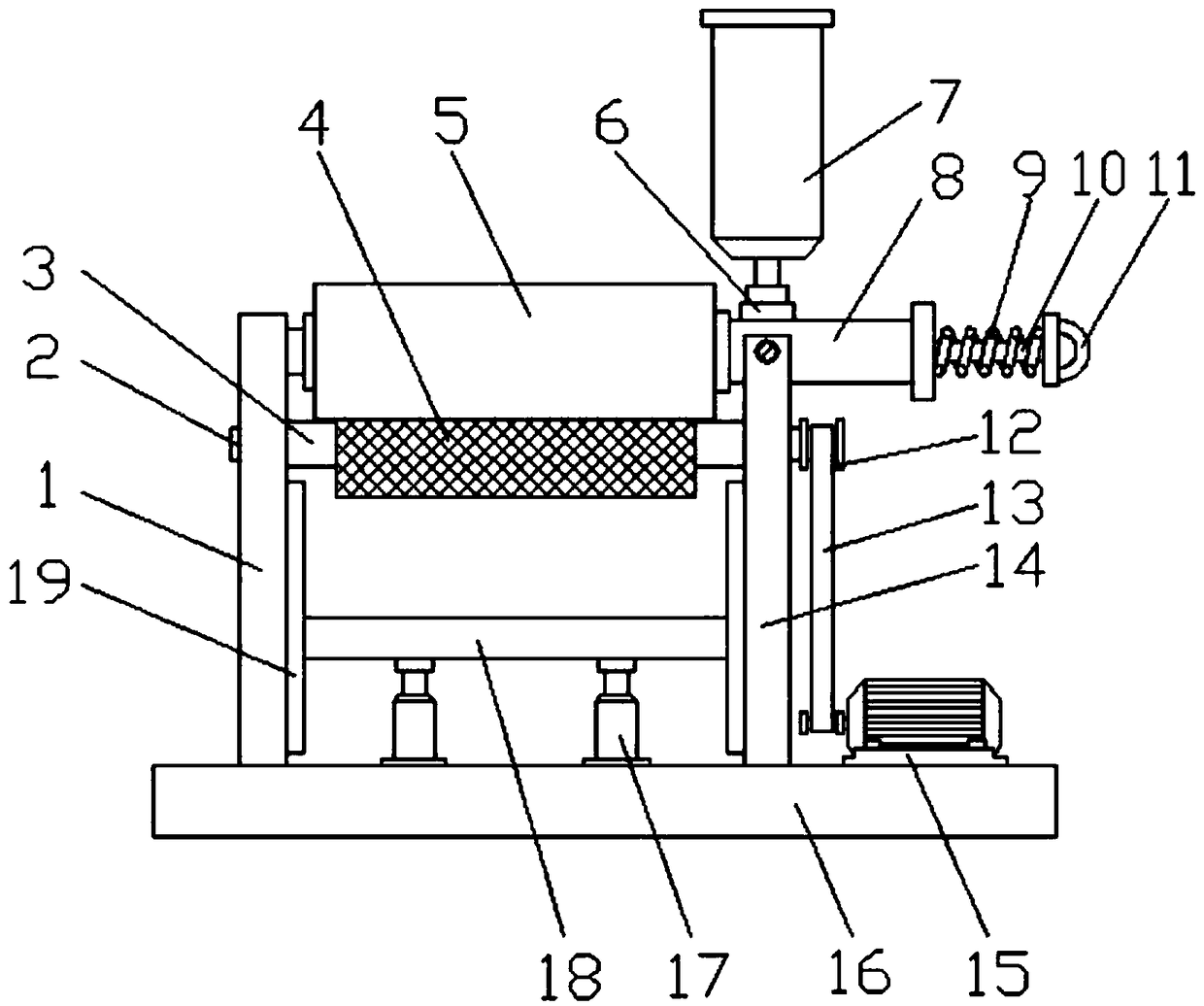
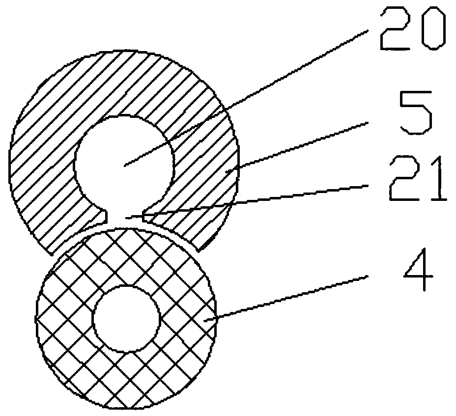
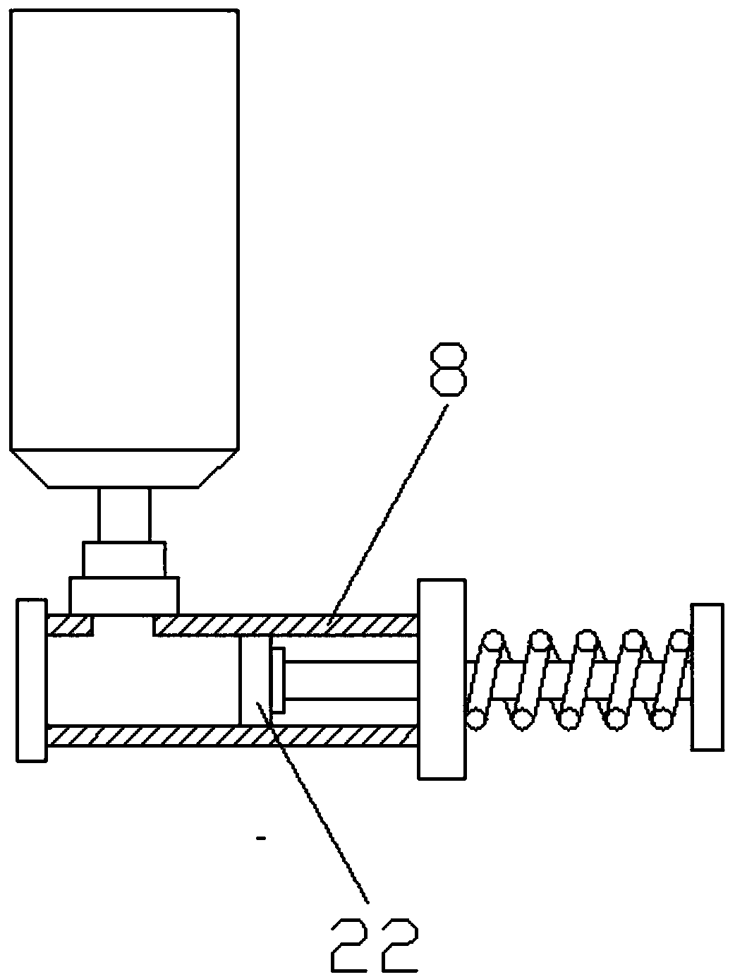
[0014] see Figure 1-3 , in an embodiment of the present invention, a roller coating device for valve parts, comprising a left fixed frame 1, a rotating shaft 2, a drum 4, a drum loading mechanism 5, a feeding mechanism 8, a right fixed frame 14, a drive motor 15 and Device base 16, the top surface both sides of described device base 16 are respectively welded with left fixed mount 1 and right fixed mount 14, described left fixed mount 1 and right fixed mount ...


PUM


Abstract

The invention discloses a roller coating device for valve parts. The roller coating device comprises a left fixed frame, a rotating shaft, a roller, a roller loading mechanism, a feeding mechanism, aright fixed frame, a drive motor and a device base; the left fixed frame and the right fixed frame are welded to the two sides of the top surface of the device base correspondingly, and are symmetrically arranged, the roller loading mechanism is arranged on the upper portion of the position between the left fixed frame and the right fixed frame, one end of the roller loading mechanism is welded tothe surface of the left fixed frame, the feeding mechanism is welded to the surface of the other end of the roller loading mechanism, and the feeding mechanism is fixed to the right fixed frame through a screw; due to the fact that the feeding power of the feeding mechanism derives from shrinkage of a tension spring, consumption of the feeding mechanism for power is reduced, consumption of powerof the roller coating device is reduced, the device is simple in structure, and the technical needs of a worker are reduced.

Description

technical field [0001] The invention relates to the technical field of roller coating devices, in particular to a roller coating device for valve parts. Background technique [0002] "Roller coating machine" is an important equipment in the series of coating equipment, which has the advantages of small paint loss, high production efficiency, simple and convenient maintenance; it can be well connected with the assembly line to form a production line with a high degree of automation; it is especially suitable for The coating of NC paint and UV paint has the best effect; it is also suitable for the coating of PU paint and PE paint, but the requirements for rubber rollers are higher, the cleaning machine is more troublesome, and the operation is not too convenient. The existing roller coating machine has a complex structure and many electrical equipments, consumes a lot of power when the machine is running, and the operation process is relatively complicated, which requires user...

Claims


Application Information

Patent Timeline
Patent Type & Authority Applications(China)
IPC IPC(8): B05C1/10B05C1/08B05C13/02
CPCB05C1/10B05C1/0813B05C1/0821B05C1/0865B05C13/02
Inventor 徐通马恒
Owner 徐通
Why Eureka
Try Eureka