
Vehicle-mounted fire extinguisher support

A fire extinguisher and vehicle-mounted technology, which is applied in fire rescue and other directions, can solve problems such as reducing the service life of fire extinguishers, delaying fire extinguishing time, safety accidents, etc., and achieves the effects of fast and convenient installation and access, prolonging service life and ensuring stability

Pending Publication Date: 2018-10-12
海盐巨龙消防设备有限公司
View PDF8 Cites 0 Cited by
  • Summary
  • Abstract
  • Description
  • Claims
  • Application Information

AI Technical Summary

Problems solved by technology

[0002] The people's awareness of fire protection has increased. To ensure safety, most public places need to be equipped with fire extinguishers, and most motor vehicles will also be equipped with fire extinguishers. However, vehicle-mounted fire extinguishers are generally placed in the trunk at will. Rolling back and forth may cause unintentional triggering of the fire extinguisher switch, causing safety accidents, affecting the life of the fire extinguisher and causing waste
However, because most of the existing fire extinguisher brackets are clamping or sleeve-type, it is easy to wear the surface layer of the fire extinguisher bottle when taking the fire extinguisher, which reduces the service life of the fire extinguisher and cannot meet the requirements for quickly taking the fire extinguisher. Physical exertion delays the fire extinguishing time and fire situation, and each bracket can only meet the placement requirements of a specific size of fire extinguisher, so the scope of application is small

Method used


Image

  • Vehicle-mounted fire extinguisher support
  • Vehicle-mounted fire extinguisher support

Examples


Embodiment Construction

[0016] In order to make the object, technical solution and advantages of the present invention clearer, the present invention will be further described in detail below with reference to the accompanying drawings and embodiments. However, it should be understood that the specific embodiments described here are only used to explain the present invention, and are not intended to limit the scope of the present invention. Also, in the following description, descriptions of well-known structures and techniques are omitted to avoid unnecessarily obscuring the concept of the present invention.

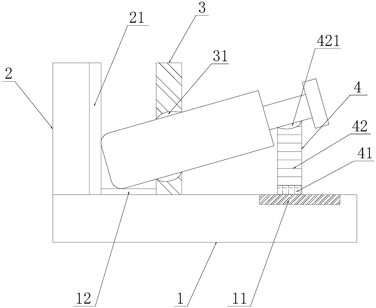
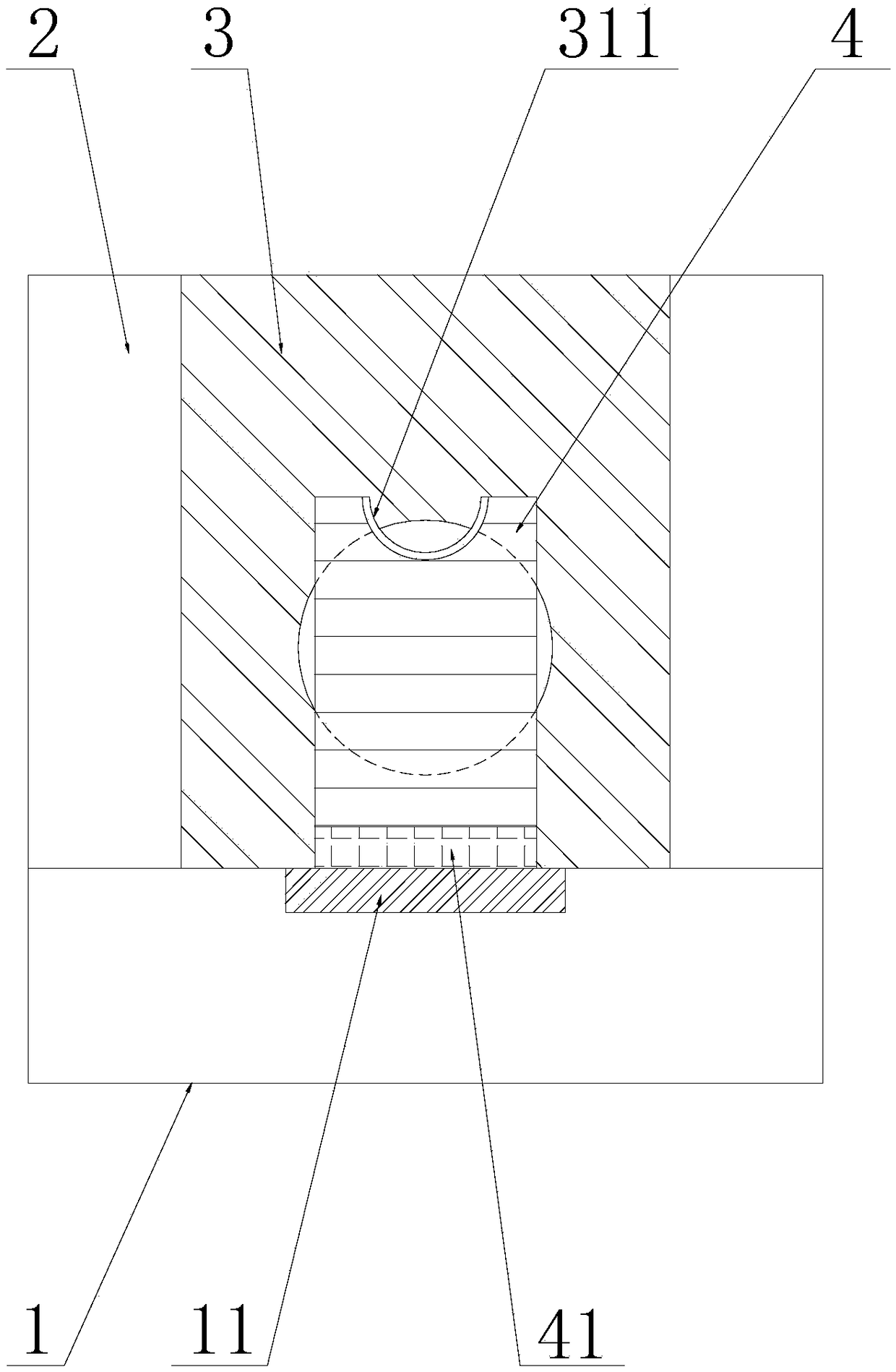
[0017] refer to figure 1 with figure 2 , the embodiment of the present invention provides a vehicle-mounted fire extinguisher bracket, including a base plate 1, a longitudinal base plate 2, a fixed placement plate 3 and a movable support plate 4, the longitudinal base plate 2 is installed and fixed on the base plate 1, and the base plate 1 is provided with There is a moving slide rail 11, t...


PUM


Abstract

The invention discloses a vehicle-mounted fire extinguisher support which comprises a bottom plate, a longitudinal base plate, a fixed placing plate and a movable supporting plate. The bottom plate isprovided with a movable sliding rail, the lower end of the movable supporting plate is provided with a movable sliding wheel matched with the movable sliding rail, a pretightening spring is arrangedin the movable supporting plate, the upper end of the pretightening spring is provided with a handle containing groove for containing a handle at the upper end of a fire extinguisher, and the fixed placing plate is provided with a fire extinguisher bottle body containing groove. Since a bottle body of the fire extinguisher is inserted into the fire extinguisher bottle body containing groove, the bottle bottom of the fire extinguisher abuts against a transverse elastic gasket and a longitudinal elastic gasket, stability of the fire extinguisher is ensured, an elastic washer on the inner side wall of the fire extinguisher bottle body containing groove prevents abrasion caused by friction to the bottle body of the fire extinguisher, and the service life of the fire extinguisher is prolonged.The position of the movable supporting plate is flexibly adjusted to be applicable to fire extinguishers with different heights, the handle at the upper end of the fire extinguisher obliquely abuts against the handle containing groove, and placing stability of the fire extinguisher is further ensured.

Description

【Technical field】 [0001] The invention relates to the technical field of fire extinguisher accessories, in particular to a vehicle-mounted fire extinguisher bracket. 【Background technique】 [0002] The people's awareness of fire protection has been strengthened. In order to ensure safety, most public places need to be equipped with fire extinguishers, and most motor vehicles will also be equipped with fire extinguishers. However, vehicle-mounted fire extinguishers are generally placed in the trunk at will. Rolling back and forth may cause unintentional triggering of the fire extinguisher switch, causing safety accidents, affecting the life of the fire extinguisher and causing waste. However, because most of the existing fire extinguisher brackets are clamping or sleeve-type, it is easy to wear the surface of the fire extinguisher bottle when taking the fire extinguisher, which reduces the service life of the fire extinguisher and cannot meet the requirements for quickly taki...

Claims


Application Information

Patent Timeline
Patent Type & Authority Applications(China)
IPC IPC(8): A62C13/78A62C3/07
CPCA62C3/07A62C13/78
Inventor 唐东升
Owner 海盐巨龙消防设备有限公司
Learn More