
Bandwidth adjusting method and device

A technology of bandwidth adjustment and bandwidth, applied in the field of communication, can solve problems such as no bandwidth adjustment method

Active Publication Date: 2018-10-09
HUAWEI TECH CO LTD
View PDF5 Cites 25 Cited by
  • Summary
  • Abstract
  • Description
  • Claims
  • Application Information

AI Technical Summary

Problems solved by technology

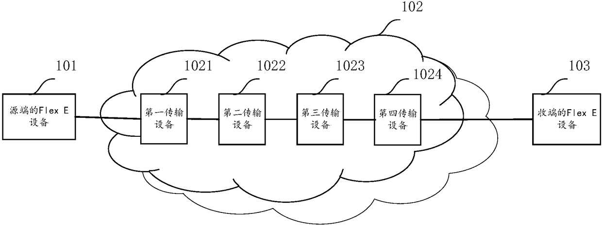
[0005] The maturity of the above technologies makes it possible to have a rigid pipe with end-to-end variable bandwidth and good granularity. However, this end-to-end pipe is composed of relatively independent Flex E, FlexOTN, and FlexGrid / superchannel. Because of Flex E, FlexOTN, FlexGrid / superchannel each have their own bandwidth change granularity and methods. For this end-to-end pipeline, there is currently no bandwidth adjustment method to adapt to the changing requirements of bandwidth service traffic

Method used


Image

  • Bandwidth adjusting method and device
  • Bandwidth adjusting method and device
  • Bandwidth adjusting method and device

Examples


Embodiment 1

[0126] Figure 5 It is a schematic flow diagram corresponding to a bandwidth adjustment method provided in this application, and the bandwidth adjustment is described based on the perspective of the source access device, as shown in Figure 5 As shown, the method includes:

[0127] Step 501, the source access device obtains optical layer channel bandwidth adjustment information and electrical layer channel time slot adjustment information, wherein the electrical layer channel time slot adjustment information is obtained from the first flexible Ethernet Flex E frame; The optical layer channel bandwidth adjustment information indicates to adjust the optical layer channel bandwidth, and the electrical layer channel time slot adjustment information indicates to adjust the electrical layer channel time slot;

[0128] Step 502, the source access device sends the optical layer channel bandwidth adjustment information and electrical layer channel time slot adjustment information to t...

Embodiment 2

[0153] In Embodiment 2, the situation of cooperatively adjusting bandwidth increase in the first possible implementation manner of Embodiment 1 is described.

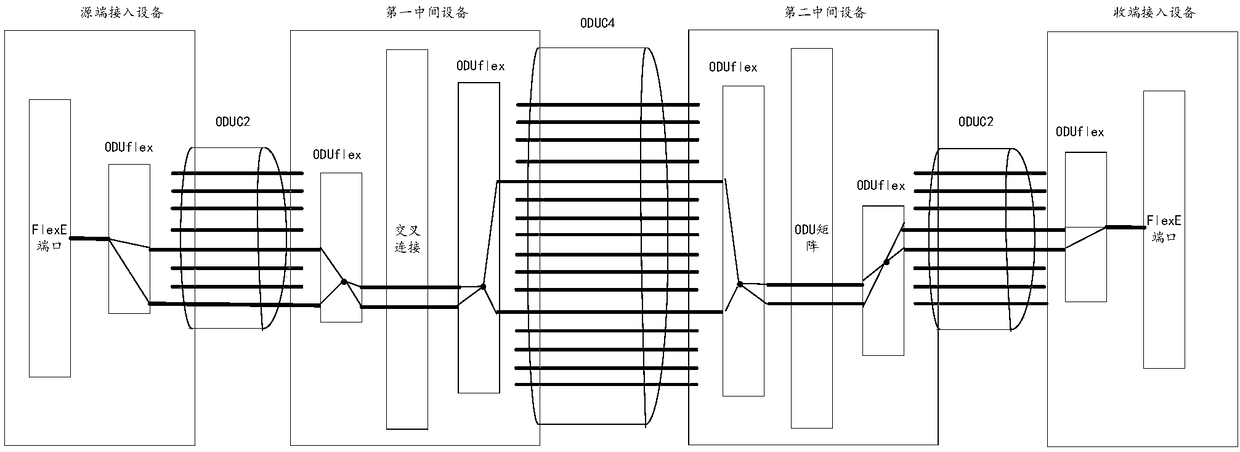
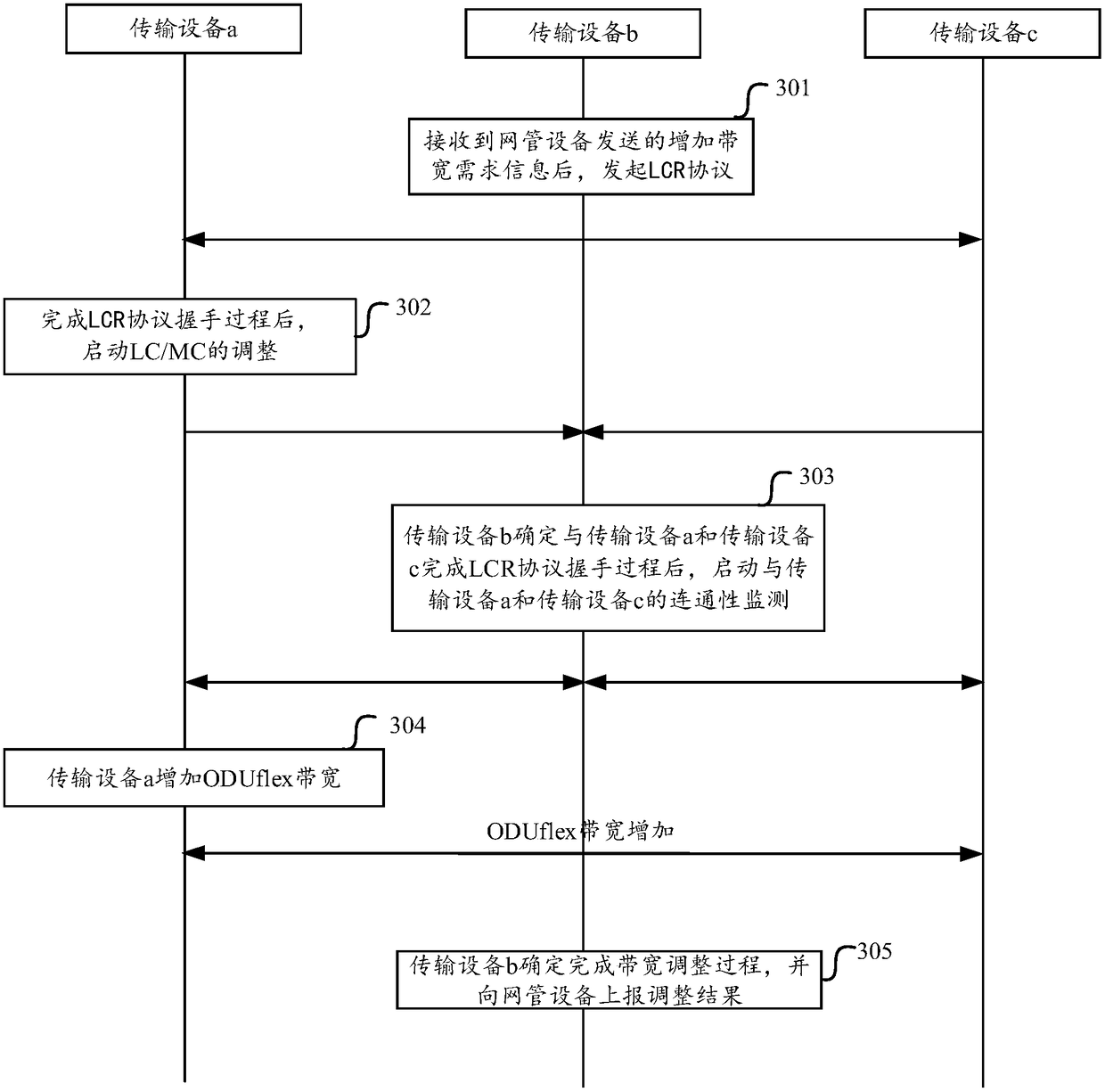
[0154] Specifically, the process of cooperatively adjusting the bandwidth increase is divided into three steps: the first step is to complete the handshake and adjustment of the optical layer channel; the second step is to complete the time slot increase of ODUCn and the channel verification of ODUflex; the third step , complete the switching of the time slot configuration, and complete the bandwidth adjustment process. Each step is described in detail below.

[0155] first step:

[0156] Figure 7a It is a schematic diagram of the first stage of the first step. Such as Figure 7a As shown, the source access device obtains the optical layer channel bandwidth requirement and electrical layer channel time slot adjustment information, for example, the optical layer channel bandwidth requirement is 200G (that is, the op...

Embodiment 3

[0181] In Embodiment 3, a situation of cooperatively adjusting bandwidth reduction in the first possible implementation manner of Embodiment 1 is described.

[0182] Specifically, the process of cooperatively adjusting the bandwidth reduction is divided into three steps: the first step is to complete the ODUCn time slot reduction and the ODUflex channel verification; the second step is to complete the configuration switching of the new time slot; the third step is to Complete the bandwidth adjustment process if the bandwidth of the optical layer channel is less. Each step is described in detail below.

[0183] first step:

[0184] The source access device obtains the optical layer channel bandwidth requirement and electrical layer channel time slot adjustment information, for example, the optical layer channel bandwidth requirement is 90G (that is, the optical layer channel bandwidth needs to be reduced to 90G), In order to reduce a time slot. According to the adjustment in...


PUM


Abstract

The invention discloses a bandwidth adjusting method and device. The method comprises that a source-end access device obtains optical layer channel bandwidth adjusting information and electric layer channel time slot adjusting information from a first flexible Ethernet Flex E frame, the optical layer channel bandwidth adjusting information and electric layer channel time slot adjusting informationis sent to a neighbor device of the source-end access device via a first OTN frame, optical layer channel bandwidth adjustment confirming information and electric layer channel time slot adjustment confirming information are received from the neighbor device via a second OTN frame, and the optical layer channel bandwidth is adjusted according to the optical layer bandwidth updating information, the electric layer channel time slot is adjusted according to the electric layer channel time slot adjusting information, so that the optical layer channel bandwidth and the electric layer channel timeslot after adjustment satisfy a service bandwidth adjusting requirement. The utilization rate of the data transmission channel can be improved, high-efficiency bearing of the Ethernet service is satisfied, and an adjusting process is simpler and rapider.

Description

technical field [0001] The invention relates to the field of communication technology, in particular to a bandwidth adjustment method and device. Background technique [0002] The Flex Ethernet Project (Flexible Ethernet Project) was released at the quarterly meeting of the 2015 Optical Internet Forum OIF. This project defines a more flexible Ethernet to make full use of the capacity of optical connections and achieve the purpose of establishing faster connections. Based on the Ethernet IEEE standard, Flex Ethernet introduces channelization technology to optimize Ethernet, realizes the decoupling of the MAC rate and the IEEE Ethernet physical interface standard, and facilitates the independent evolution of the Ethernet MAC rate. [0003] According to the Flex E service protocol, the data format of the Flex E service data is an encapsulation format specified by the Flex E protocol on the basis of the original Ethernet packet data format. In the Flex E service transmission sc...

Claims


Application Information

Patent Timeline
IPC IPC(8): H04L12/24H04L5/00
CPCH04L5/0078H04L41/0896
Inventor 向俊凌田大锋魏建英
Owner HUAWEI TECH CO LTD
Learn More