Controller applied to power converter and operating method thereof

A technology of power converters and operating methods, applied in the direction of high-efficiency power electronic conversion, output power conversion devices, electrical components, etc., capable of solving problems such as poor correction efficiency

Inactive Publication Date: 2018-10-09
LEADTREND TECH
View PDF7 Cites 0 Cited by
  • Summary
  • Abstract
  • Description
  • Claims
  • Application Information

AI Technical Summary

Problems solved by technology

However, because the input voltage of the boost converter varies with the load of the boost converter, only a single mode (discontinuous conduction mode, continuous conduction mode or interleaved mode) of the boost converter can be operated. The power factor correction efficiency of the converter may become worse as the input voltage of the boost converter changes
Therefore, the boost converter with power factor correction disclosed in the prior art still has a lot of room for improvement

Method used


Image

  • Controller applied to power converter and operating method thereof
  • Controller applied to power converter and operating method thereof
  • Controller applied to power converter and operating method thereof

Examples


Embodiment Construction

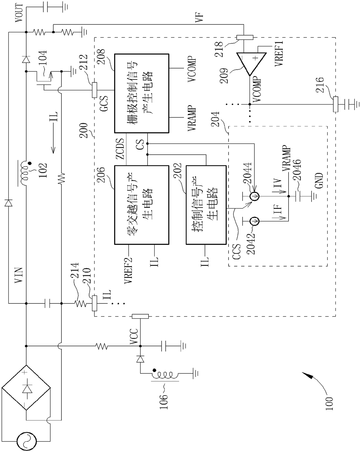
[0058] Please refer to figure 1 , figure 1 It is a schematic diagram of a controller 200 applied to the power converter 100 disclosed in the first embodiment of the present invention, wherein the controller 200 includes a control signal generating circuit 202, a slope voltage generating circuit 204, a zero-crossing signal The generation circuit 206 and a gate control signal generation circuit 208, and the control signal generation circuit 202 are coupled to the slope voltage generation circuit 204, the zero-crossing signal generation circuit 206 and the gate control signal generation circuit 208, and the slope voltage generation circuit 204 is additionally It is coupled to the gate control signal generating circuit 208 , and the zero-crossing signal generating circuit 206 is further coupled to the gate control signal generating circuit 208 . In addition, the power converter 100 is a power factor correction (Power Factor Correction, PFC) boost converter. Such as figure 1 As ...


PUM


Abstract

The invention discloses a controller applied to a power converter and an operating method thereof. The controller comprises a control signal generating circuit and a grid control signal generating circuit, wherein the control signal generating circuit is used for generating a control signal when the input voltage inputted into the power converter is greater than a predetermined voltage; and the grid control signal generating circuit is coupled to the control signal generating circuit, the grid control signal generating circuit generates a grid control signal corresponding to a continuous conduction mode of the power converter to a power switch of the power converter when the grid control signal generating circuit receives the control signal, and the power switch is turned on or off according to the grid control signal. Compared with the prior art, the controller has the advantages that the magnetic utilization ratio of an inductor of the power converter is increased, the power factor correction efficiency of the power converter is improved, and that the output power of the power converter is increased.

Description

technical field [0001] The present invention relates to a controller applied to a power converter and its operation method, in particular to a method of using the turn-on time of the power switch of the power converter to determine whether to switch the operation mode of the power converter to improve the performance of the power converter. A power factor corrected efficiency controller and method of operation thereof. Background technique [0002] The power factor correction (Power Factor Correction, PFC) boost converter disclosed in the prior art can only operate in the discontinuous conduction mode (Discontinuous Conduction Mode, DCM), or operate in the continuous conduction mode (Continuous Conduction Mode, CCM), or operate in interleaved mode (Interleaved Mode). However, because the input voltage of the boost converter varies with the load of the boost converter, only a single mode (discontinuous conduction mode, continuous conduction mode or interleaved mode) of the b...

Claims


Application Information

Patent Timeline
IPC IPC(8): H02M1/08H02M1/42
CPCH02M1/08H02M1/4225Y02B70/10
Inventor 邹明璋王昱斌
Owner LEADTREND TECH
Why Eureka
Try Eureka