
A device for continuous collection of surface water by a scientific research ship during its voyage

A technology for surface water and scientific research ships, applied in the field of scientific research ships, can solve problems such as inability to collect surface water, trawling underwater objects, and hose floating.

Active Publication Date: 2020-07-07
THE FIRST INST OF OCEANOGRAPHY SOA
View PDF6 Cites 0 Cited by
  • Summary
  • Abstract
  • Description
  • Claims
  • Application Information

AI Technical Summary

Problems solved by technology

[0006] The box type is generally used in static sampling. In dynamic sampling, the position of the box body cannot be artificially fixed due to the resistance of the water, and it is easy to rub against the hull and cause damage due to impact. The method of trawling is easy to entangle with underwater objects, such as breeding area or some floating objects, it is also impossible to take stable samples for a long time
At present, the continuous sampling method of the scientific research ship during the voyage is generally to install one or more sampling tubes on the side of the ship, extend the sampling tubes into the seawater 20-30cm below the water surface, and use the pumping equipment to pass the sampling tubes to the position. The surface seawater is collected on the ship, but there are some problems with this sampling method. First, the scientific research ship has a certain speed when sailing, and the hose will be continuously resisted by the seawater when collecting the surface seawater. Floating up, it is impossible to collect surface water; second, the traditional metal sampling tubes have continuous resistance to the seawater due to the long-term voyage of the scientific research ship, which will bend the sampling tubes and cause damage, and how to lower the metal sampling tubes to Underwater and fixed is a difficult problem to solve

Method used


Image

  • A device for continuous collection of surface water by a scientific research ship during its voyage
  • A device for continuous collection of surface water by a scientific research ship during its voyage
  • A device for continuous collection of surface water by a scientific research ship during its voyage

Examples


Embodiment Construction

[0020] Below in conjunction with accompanying drawing and specific embodiment the present invention is described in further detail;

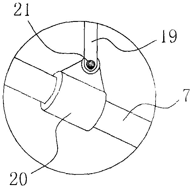
[0021] Such as figure 1 , 2 , 3, and 4, a device for continuous collection of surface water by a scientific research ship during navigation, the device 4 includes 5 rail parts laid up and down along the ship's side 2 and a rotating part 6 arranged on one side of the rail part 5, A sampling rod 7 that can swing up and down along the side of the ship 2 is arranged between the track part 5 and the rotating part 6. One end of the sampling rod 7 is connected to the rotating part 6 in rotation, and the other end is slidably connected to the track part 5, wherein the track part 5 includes a slide rail 8, a slideway 9 is provided along the length direction of the slide rail 8, and a slide block 10 slidingly matched with the slideway 9 is connected to the sampling rod 7, and the slide block 10 is rotationally connected with the sampling rod 7. The rota...


PUM

PropertyMeasurementUnit
diameteraaaaaaaaaa
particle diameteraaaaaaaaaa

Abstract

The invention discloses a device for continuously collecting superficial water for a scientific research ship in the underway process. The device comprises a track component and a rotating component,wherein the track component is vertically paved along a ship rail; the rotating component is arranged on one side of the track component; a sampling rod which can swing along the upper part and the lower part of the ship rail is arranged between the track component and the rotating component; one end of the sampling rod is rotationally connected with the rotating component; the other end of the sampling rod is connected with the track component in a sliding manner; a sampling pipe which extends into the superficial water and is used for sucking and sampling the superficial water is fixed on the sampling rod; a hydraulic cylinder for driving the sampling rod to rotate around the rotating component and slide along the track component for swinging the sampling pipe to the position of the superficial water is arranged on the ship rail; and a buffer mechanism for preventing the damage to the sampling pipe caused by continuous resistance generated by seawater during underway of a ship hull is arranged on the sampling pipe. The device disclosed by the invention can effectively ensure that the superficial water can be accurately collected and realizes continuous collection in the underwayprocess of the scientific research ship.

Description

technical field [0001] The invention relates to the technical field of scientific research ships, in particular to a device for continuously collecting surface water during the sailing process of the scientific research ships. Background technique [0002] Microplastics, which are plastic particles with a diameter of less than 5 mm, are a major carrier of pollution. Microplastics include polyethylene, polypropylene, polyvinyl chloride, polystyrene, polyurethane, polyamide, polyethylene terephthalate, etc. Microplastics are small in size, which means higher specific surface area (specific surface area refers to the surface area per unit mass of porous solid matter). The larger the specific surface area, the stronger the ability to adsorb pollutants. First of all, there are already a large number of persistent organic pollutants such as PCBs and bisphenol A in the environment (these organic pollutants are often hydrophobic, which means that they are not easily dissolved in wa...

Claims


Application Information

Patent Timeline
Patent Type & Authority Patents(China)
IPC IPC(8): G01N1/14G01N1/34
CPCG01N1/14G01N1/34
Inventor 张志平张浩然李杨
Owner THE FIRST INST OF OCEANOGRAPHY SOA
Learn More