Bearing gland at end of submersible pump rotor shaft

A technology for bearing glands and rotor shafts, which is applied to components, pumps, pump devices, etc. of pumping devices for elastic fluids. It can solve the problems of high loss costs, bearing wear, and damage to motors, and avoid mutual scratches. The effect of reducing maintenance cost and prolonging service life

Inactive Publication Date: 2018-10-09
WEINAN GENERAL EQUIP MFG
View PDF0 Cites 0 Cited by
  • Summary
  • Abstract
  • Description
  • Claims
  • Application Information

AI Technical Summary

Problems solved by technology

In the original structure, the bottom end of the bearing gland has only a thinner wall thickness, which cannot provide auxiliary support for the rotor shaft. Furthermore, in some groundwater environments with large sediment, fine sand particles will cause serious damage to the bearing. Large wear, once the bearing is damaged and the gap increases, the rotor will swing. Since the gap between the rotor and the stator is small, once the rotor swings, the rotor and the stator will scratch each other, which will damage the motor and cause the submersible pump to be scrapped. , the cost of loss is large

Method used


Image

  • Bearing gland at end of submersible pump rotor shaft
  • Bearing gland at end of submersible pump rotor shaft

Examples


Embodiment Construction

[0012] A bearing gland at the rotor shaft end of a submersible pump according to the present invention will be further described below in conjunction with the accompanying drawings and specific embodiments:

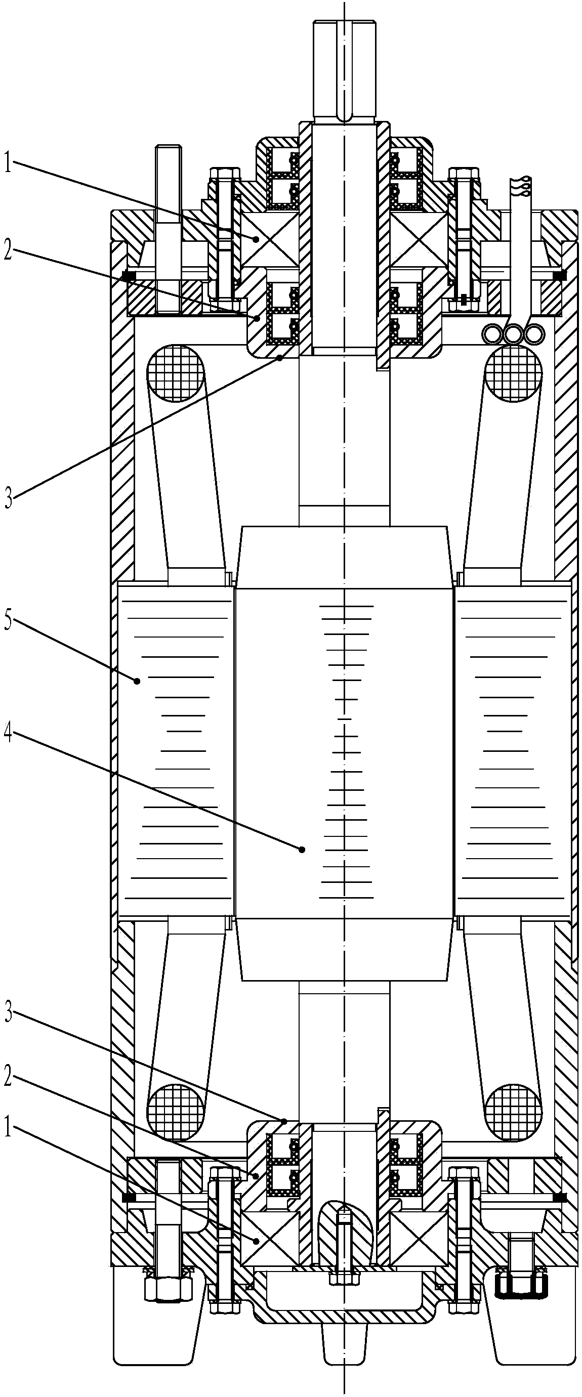
[0013] figure 1 It is a structural schematic diagram of the bearing gland at the shaft end of the original submersible pump rotor. In the figure, the bottom end 3 of the bearing gland 2 has only a thinner wall thickness, which cannot provide auxiliary support for the rotor 4 axis. Furthermore, in some sediments In a large groundwater environment, the fine sand particles will cause great wear to the bearing 1. Once the bearing 1 is damaged and the gap increases, the rotor 4 will swing. Since the gap between the rotor 4 and the stator 5 is small, the rotor 4 Once it swings, the rotor 4 and the stator 5 will rub against each other, thereby damaging the motor.

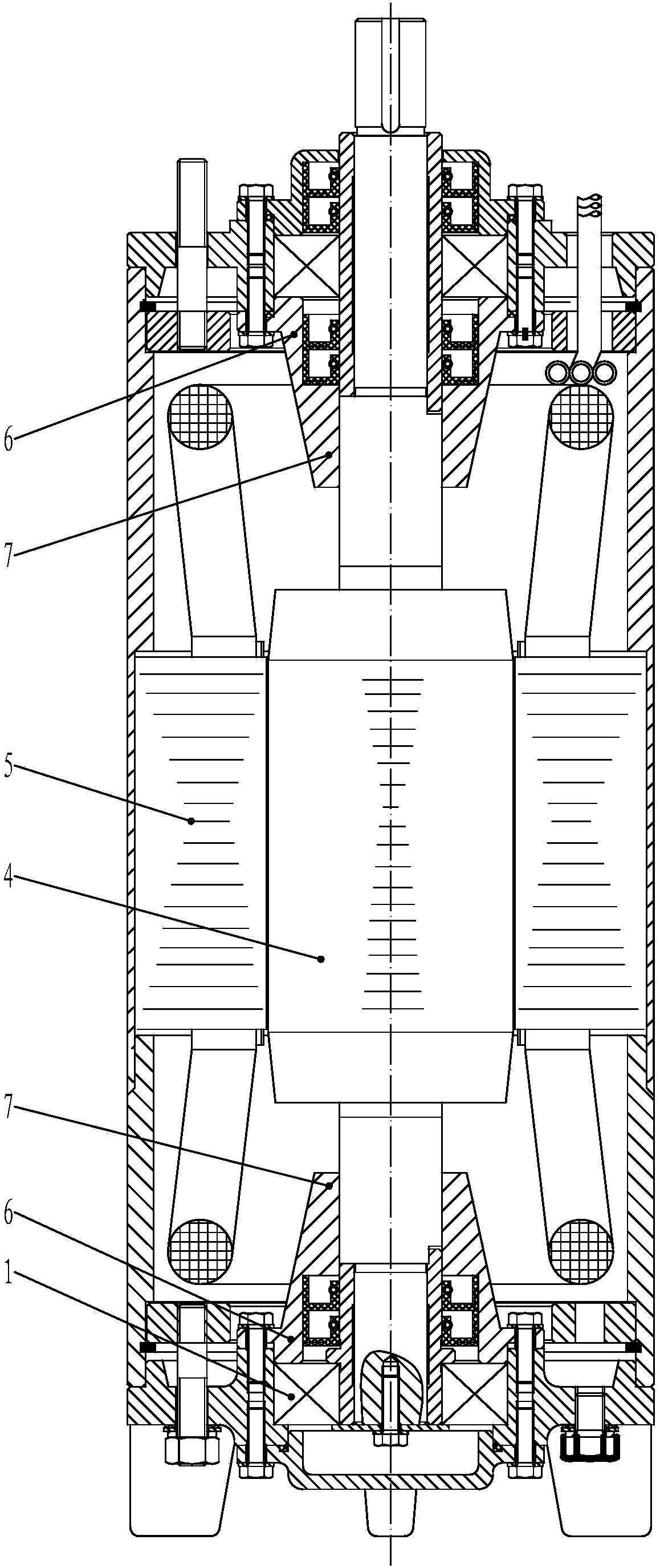
[0014] figure 2 It is a structural schematic diagram of the bearing gland at the rotor shaft end of the submersi...


PUM


Abstract

The invention provides a bearing gland at the end of a submersible pump rotor shaft. The bottom end of the bearing gland is thickened in the wall thickness direction, the thickened bottom end of the bearing gland forms a protective jacket relative to the rotor shaft, and an inner hole of the protective jacket is in sliding fit with the diameter of the rotor shaft. After a bearing is abraded and damaged, the protective jacket of the bearing gland can play a temporary supporting role for the rotor shaft, a rotor cannot swing, the situation that the rotor and a stator scratch and rub each other is avoided, and a role of protecting a motor is achieved.

Description

technical field [0001] The invention relates to a submersible pump, more specifically to a bearing gland at the rotor shaft end of the submersible pump. Background technique [0002] The submersible pump drives the impeller to run through the high-speed rotation of the rotor, pumping up the groundwater continuously. In the structure of the submersible pump, the two shaft ends of the rotor are respectively fixed by bearings, and there are bearing glands on the end faces of the bearings. In the original structure, the bottom end of the bearing gland has only a thinner wall thickness, which cannot provide auxiliary support for the rotor shaft. Furthermore, in some groundwater environments with large sediment, fine sand particles will cause serious damage to the bearing. Large wear, once the bearing is damaged and the gap increases, the rotor will swing. Since the gap between the rotor and the stator is small, once the rotor swings, the rotor and the stator will rub against eac...

Claims


Application Information

Patent Timeline
Patent Type & Authority Applications(China)
IPC IPC(8): F04D29/04F04D13/08
CPCF04D29/04F04D13/08
Inventor 田建中
Owner WEINAN GENERAL EQUIP MFG
Why Eureka
Try Eureka