
Automatic steel bar cutting-off device capable of adjusting cut-off length

A shearing device and steel bar technology, applied in the field of steel bar automatic shearing device, can solve the problems of slowing down construction efficiency, easy fatigue of staff, waste of time, etc., to avoid excessive lifting or falling, reduce manual labor, Ease of use

Active Publication Date: 2018-10-02
广西盛畅物流有限公司
View PDF5 Cites 8 Cited by
  • Summary
  • Abstract
  • Description
  • Claims
  • Application Information

AI Technical Summary

Problems solved by technology

[0003] Steel bars are often used in civil engineering construction. For some situations that require short steel bars, manual hand-held steel bar shears are often required to cut the steel bars. The existing electric steel bar shears can already save labor, but in the process of steel bar cutting, there is still It is necessary to measure the length of the steel bar to ensure that the length of the steel bar cut each time is basically the same, so as to meet the standard. For the cutting of large batches of steel bars, this method is inefficient, wastes time, and tends to slow down the overall construction efficiency. Repeated for a long time Operation, the staff are also prone to fatigue, very inconvenient

Method used


Image

  • Automatic steel bar cutting-off device capable of adjusting cut-off length
  • Automatic steel bar cutting-off device capable of adjusting cut-off length
  • Automatic steel bar cutting-off device capable of adjusting cut-off length

Examples


Embodiment Construction

[0020] The following will clearly and completely describe the technical solutions in the embodiments of the present invention with reference to the accompanying drawings in the embodiments of the present invention. Obviously, the described embodiments are only some, not all, embodiments of the present invention. Based on the embodiments of the present invention, all other embodiments obtained by persons of ordinary skill in the art without making creative efforts belong to the protection scope of the present invention.

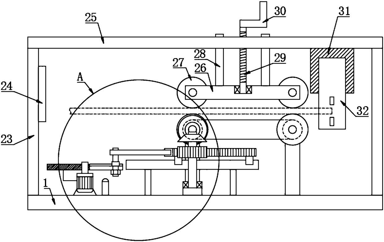
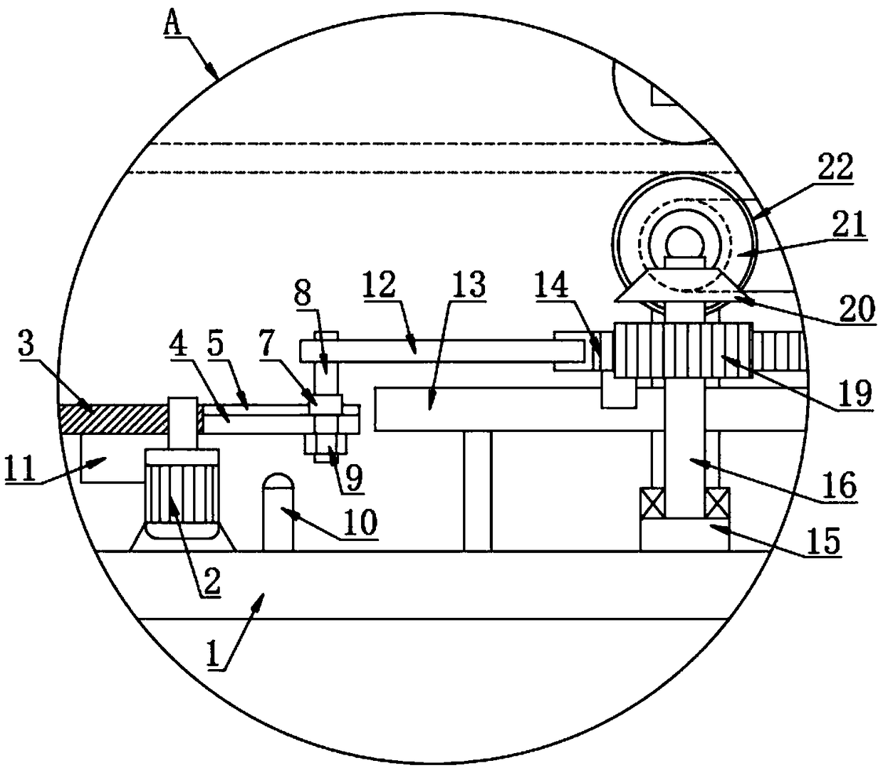
[0021] see Figure 1~5 , in an embodiment of the present invention, a steel bar automatic shearing device with adjustable cutting length includes a base 1, and two left and right driving rollers 22 are arranged on the top of the base 1 through the rotation of the bracket, and the driving rollers 22 are provided with arc-shaped grooves , to facilitate the positioning of steel bars; the left and right driving rollers 22 are connected by a belt transmission mecha...


PUM


Abstract

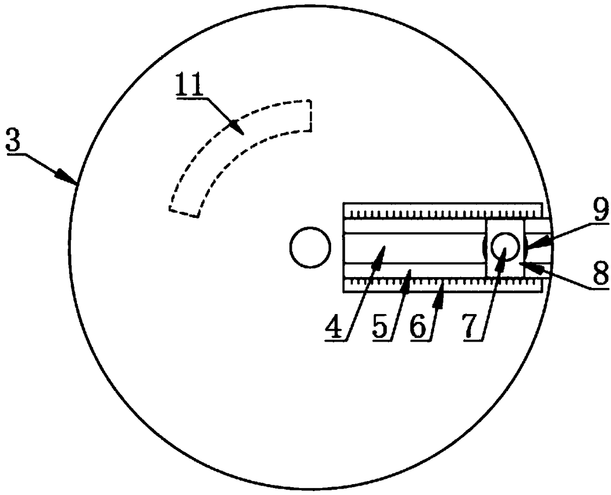
The invention discloses an automatic steel bar cutting-off device capable of adjusting the cut-off length. The automatic steel bar cutting-off device comprises a base, wherein a left transmission roller wheel and a right transmission roller wheel are rotationally arranged above the base through a support; a speed reducting motor is further arranged at the top of the base, a rotating disc is arranged on a motor shaft at the top end of the speed reducing motor, a strip-shaped opening is formed in the right side of the rotating disc, a sliding chute is formed in the top of the strip-shaped opening, a sliding block is slidably connected to the sliding chute, a positioning stud is fixedly connected to the sliding block, the top end of the positioning stud is rotationally connected with a connecting rod, and the right end of the connecting rod is hinged to the left end of a rack; and supporting rods are fixedly arranged on the left side and the right side of the top of the base respectively,a top plate is fixedly arranged at the tops of the supporting rods, a mounting seat is fixedly arranged at the bottom of the top plate, the mounting seat is arranged on the right side of the transmission roller wheels, and the top of the mounting seat is fixedly provided with an electric steel bar shear. According to the automatic steel bar cutting-off device, the distance between the positioningstud and the circle center of the rotating disc can be adjusted to adjust the cut-off length of a steel bar, the steel bar is automatically cut off by the electric steel bar shear when the steel baris stopped, so that manual control is not needed, the manual labor amount is reduced, and the use is more convenient.

Description

technical field [0001] The invention relates to the technical field of steel bar shearing, in particular to an automatic steel bar shearing device with adjustable cutting length. Background technique [0002] Civil engineering is a general term for the science and technology of building various land engineering facilities. It refers to the materials, equipment and technical activities such as surveying, design, construction, maintenance and repair, as well as the object of engineering construction. That is, various engineering facilities built on the ground or underground, on land, directly or indirectly serving human life, production, military affairs, and scientific research, such as houses, roads, railways, pipelines, tunnels, bridges, canals, dams, ports, power stations, Airports, offshore platforms, water supply and drainage, and protection projects, etc. [0003] Steel bars are often used in civil engineering construction. For some situations that require the use of s...

Claims


Application Information

Patent Timeline
IPC IPC(8): B21F11/00B21F23/00
Inventor 魏焰
Owner 广西盛畅物流有限公司
Learn More