Planar separated motor applied to wall breaking machine

A plane separation and wall breaking machine technology, which is applied in applications, electromechanical devices, electrical components, etc., can solve the problems of inconvenient placement and taking of the mixing cup, loud working noise, and short life of the motor, so as to achieve convenient cleaning and prolong The effect of long service life and convenient operation

Inactive Publication Date: 2018-09-28
AUONE ELECTRICAL CO LTD
View PDF4 Cites 7 Cited by
  • Summary
  • Abstract
  • Description
  • Claims
  • Application Information

AI Technical Summary

Problems solved by technology

[0002] Existing home appliances use the traditional motor structure, the rotor of the motor is assembled inside the stator, when it is used in electrical appliances such as wall breakers, due to the high speed of the motor, a series motor (with a commutator and brushes) is usually used, and the broken The inner cutter head part of the mixing cup of the wall breaker (hereinafter referred to as the mixing cup) needs a coupling to connect with the motor output shaft of the base of the wall breaking machine (hereinafter referred to as the base), resulting in short life of the motor, high noise and limited space It is inconvenient to place and take the mixing cup (currently the stirring cup on the market can only be taken in a vertical direction) and other difficult problems

Method used


Image

  • Planar separated motor applied to wall breaking machine
  • Planar separated motor applied to wall breaking machine
  • Planar separated motor applied to wall breaking machine

Examples


Embodiment Construction

[0026] The technical solutions of the present invention will be described below in conjunction with the drawings and embodiments.

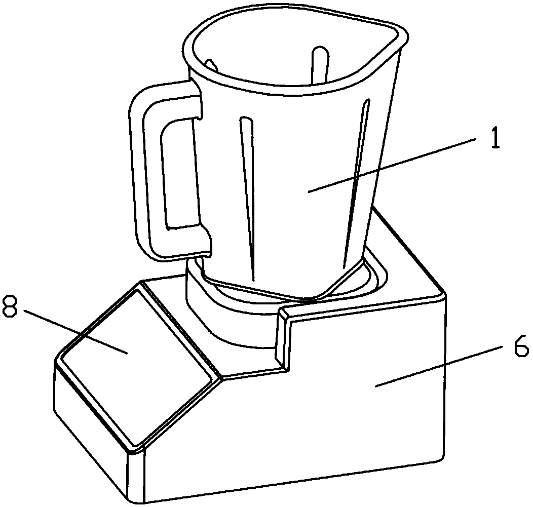
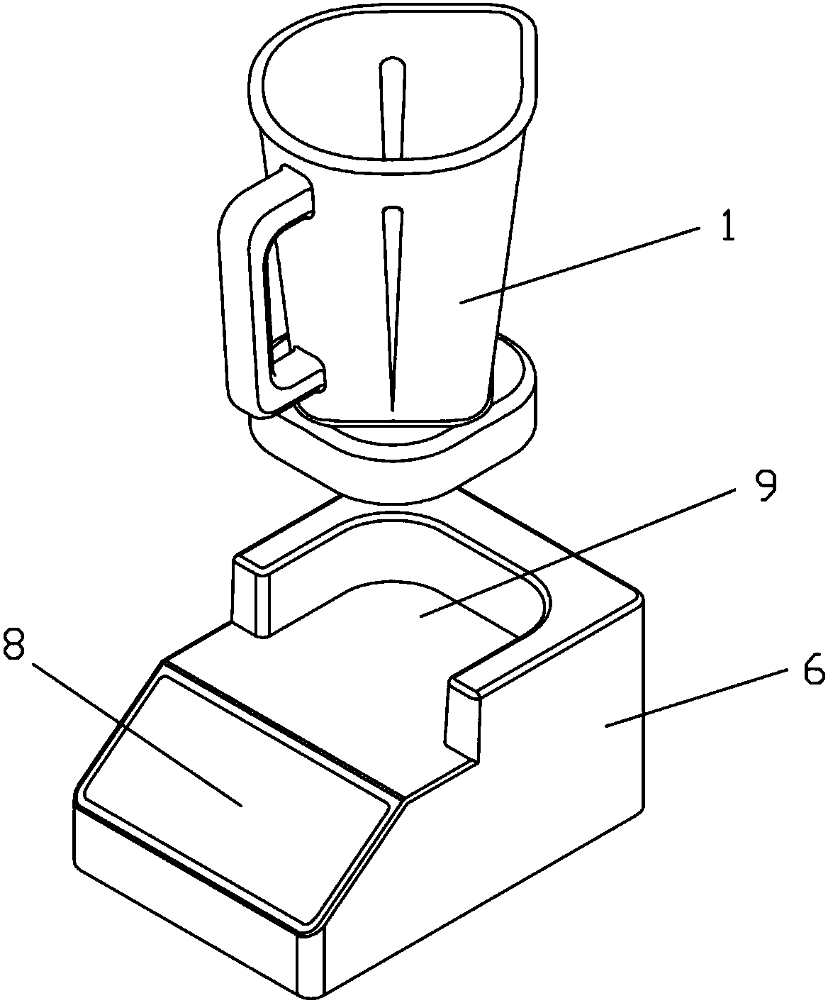
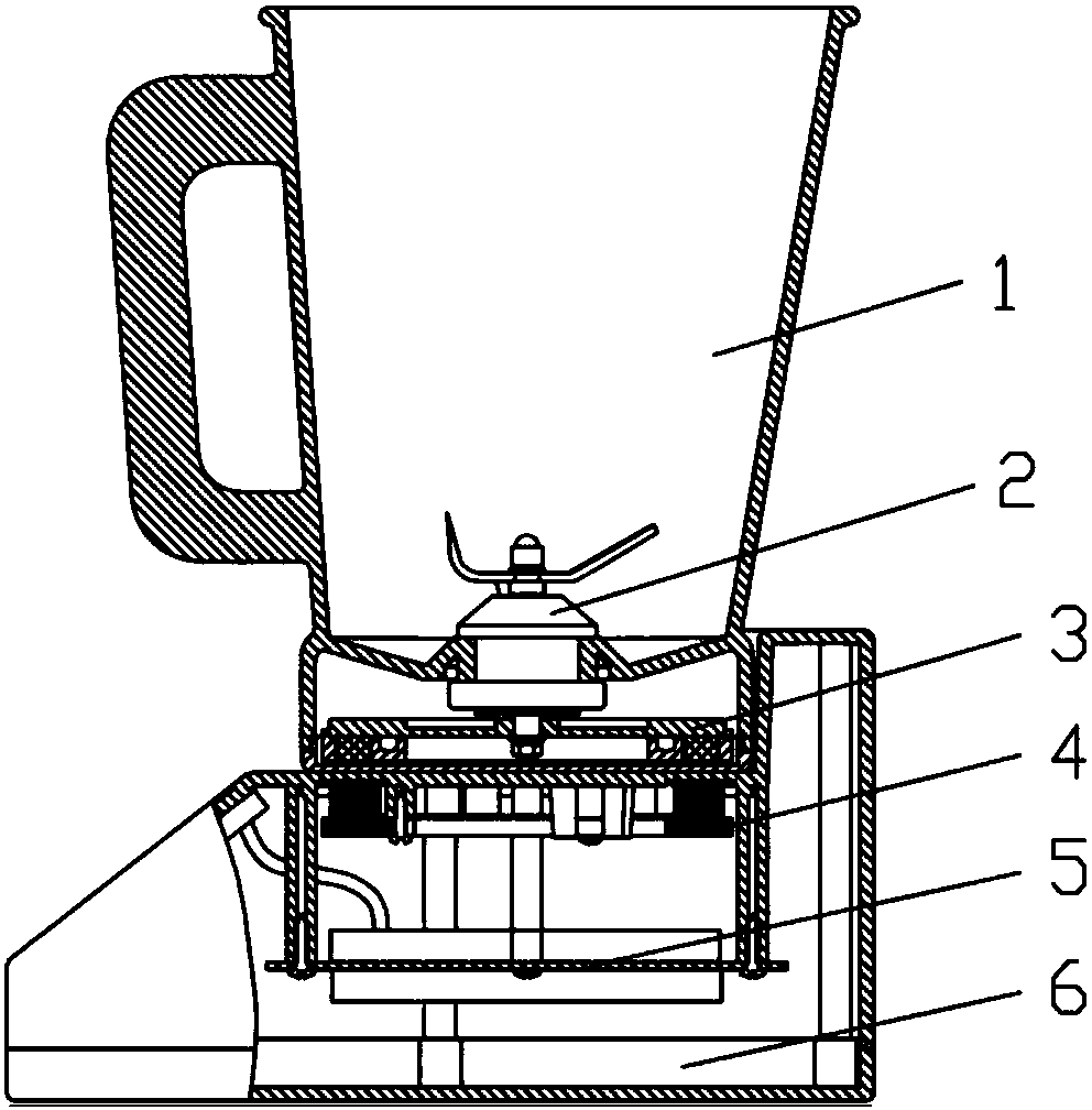
[0027] Such as Figure 1 to Figure 3 As shown, a planar split motor applied to a wall breaking machine according to the present invention includes a planar split motor rotor 3 and a planar split motor stator 4, and the planar split motor rotor 3 is arranged on the stirring cup 1 of the wall breaking machine In the cavity at the bottom, and connected with the cutter head part 2 in the mixing cup 1 through a shaft, the plane separated motor stator 4 is set in the cavity of the base 6 of the wall breaker, and is connected with the base 6 The system control part 5 is electrically connected, the bottom of the stirring cup 1 is fixed with a cup bottom cover 7, and the top of the base 6 is provided with a U-shaped seat 9, and the cup bottom cover 7 can be pushed in and taken out from the U-shaped seat 9 in the horizontal direction to realize plane separa...


PUM


Abstract

The invention relates to the technical field of motors, in particular to a planar separated motor applied to a wall breaking machine. The planar separated motor comprises a planar separated motor rotor and a planar separated motor stator, wherein the planar separated motor rotor is arranged in a hollow cavity at the bottom of a stirring cup of the wall breaking machine and is connected with a toolbit component arranged in the stirring cup as a whole through a shaft; the planar separated motor stator is arranged in a hollow cavity of a base of the wall breaking machine and is electrically connected with a system control component arranged in the base; a cup bottom cover is fixed at the bottom of the stirring cup; a U-shaped seat is arranged at the top of the base; and the stirring cup canbe pushed into the U-shaped seat and taken out of the U-shaped seat through the cup bottom cover in the horizontal direction, thereby achieving allocation positioning and separating of the planar separated motor rotor and the planar separated motor stator. By adopting the structure arrangement, compared with a traditional motor, the planar separated motor has the advantages that the planar separated motor is free of a commutator, an electric brush or a coupling, so that noise of friction and collision caused by these factors are eliminated, the service life of the motor is greatly prolonged and the operation is more convenient.

Description

technical field [0001] The invention relates to the technical field of motors, in particular to a plane-separated motor applied to a wall breaker. Background technique [0002] Existing home appliances use the traditional motor structure, the rotor of the motor is assembled inside the stator, when it is used in electrical appliances such as wall breakers, due to the high speed of the motor, a series motor (with a commutator and brushes) is usually used, and the broken The inner cutter head part of the mixing cup of the wall breaker (hereinafter referred to as the mixing cup) needs a coupling to connect with the motor output shaft of the base of the wall breaking machine (hereinafter referred to as the base), resulting in short life of the motor, high noise and limited space Sometimes the mixing cup is inconvenient to place and take (currently the stirring cup on the market can only be taken in a vertical direction) and other difficult problems to solve. Therefore, it is nec...

Claims


Application Information

Patent Timeline
Patent Type & Authority Applications(China)
IPC IPC(8): H02K7/14A47J43/08A47J43/07
CPCA47J43/0722A47J43/085H02K7/14
Inventor 欧志文姜茂雄曾群杨旭刚
Owner AUONE ELECTRICAL CO LTD
Why Eureka
Try Eureka