Sintering waste heat power generation system waste heat recovery device and application method thereof

A waste heat recovery device and waste heat power generation technology, which is applied in the field of boiler waste heat recovery, can solve problems such as poor waste heat recovery power generation effect, poor waste heat recovery effect, unreasonable design and operation mode of waste heat recovery system, etc., to increase power generation and increase The effect of waste heat recovery and the effect of reducing self-consumption rate

Pending Publication Date: 2018-09-28
MAANSHAN IRON & STEEL CO LTD
View PDF7 Cites 1 Cited by
  • Summary
  • Abstract
  • Description
  • Claims
  • Application Information

AI Technical Summary

Problems solved by technology

[0003] In the process of realizing the present invention, the inventors found that the prior art has at least the following problems: waste heat recovery and power generation effects are generally poor, and in addition to sintering production factors, waste heat recovery system design and operation mode are unreasonable, resulting in poor waste heat recovery effect The main reason

Method used


Image

  • Sintering waste heat power generation system waste heat recovery device and application method thereof
  • Sintering waste heat power generation system waste heat recovery device and application method thereof
  • Sintering waste heat power generation system waste heat recovery device and application method thereof

Examples


Embodiment Construction

[0023] In order to make the object, technical solution and advantages of the present invention clearer, the implementation manner of the present invention will be further described in detail below in conjunction with the accompanying drawings.

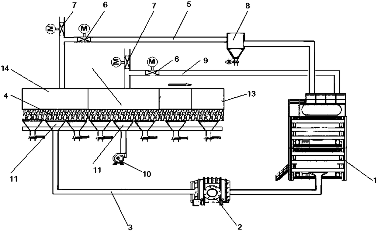
[0024] see figure 1 , a waste heat recovery device for sintering waste heat power generation system, which has:

[0025] The waste heat boiler is provided with a high-temperature flue gas inlet, a low-temperature flue gas inlet and a flue gas outlet;

[0026] A ring cooler, which includes a high temperature section of the ring cooler and a low temperature section of the ring cooler;

[0027] The gas collecting air hood is set on the ring cooler;

[0028] The high-temperature intake smoke pipe, the first end is connected to the gas collecting hood of the high-temperature section of the ring cooler, and the second end is connected to the high-temperature flue gas inlet;

[0029] The low-temperature air intake pipe, the first end is co...


PUM


Abstract

The invention discloses a sintering waste heat power generation system waste heat recovery device and an application method thereof. The sintering waste heat power generation system waste heat recovery device comprises a waste heat boiler, a circular cooling machine, a gas collection cover, a high-temperature gas inlet smoke pipe, a low-temperature gas inlet smoke pipe, a return air pipe, a circulating fan and a cooling fan, wherein the waste heat boiler is provided with a high-temperature flue gas inlet, a low-temperature flue gas inlet and a flue gas outlet; the circular cooling machine comprises a circular cooling machine high-temperature section and a circular cooling machine low-temperature section; the gas collection cover is arranged on the circular cooling machine; the first end ofthe high-temperature gas inlet smoke pipe is connected to the portion, at the circular cooling machine high-temperature section, of the gas collection cover, and the second end of the high-temperature gas inlet smoke pipe is connected with the high-temperature flue gas inlet; the first end of the low-temperature gas inlet smoke pipe is connected to the portion, at the circular cooling machine low-temperature section, of the gas collection cover, and the second end of the low-temperature gas inlet smoke pipe is connected with the low-temperature flue gas inlet; the first end of the return airpipe is connected with the circular cooling machine high-temperature section, and the second end of the return air pipe is connected with the flue gas outlet of the waste heat boiler; the circulatingfan is arranged on the return air pipe; the cooling fan is arranged on the circular cooling machine low-temperature section. Through the sintering waste heat power generation system waste heat recovery device, the waste heat recovery effect is improved, the power generating capacity is increased, the auxiliary power supply rate of a system is increased, and economic returns are increased.

Description

technical field [0001] The invention belongs to the technical field of boiler waste heat recovery, and in particular relates to a waste heat recovery device and a use method of a sintering waste heat power generation system. Background technique [0002] The waste heat power generation technology of sintered ring (belt) cooler has been widely adopted by iron and steel enterprises. [0003] In the process of realizing the present invention, the inventors found that the prior art has at least the following problems: waste heat recovery and power generation effects are generally poor, and in addition to sintering production factors, waste heat recovery system design and operation mode are unreasonable, resulting in poor waste heat recovery effect the main reason. Contents of the invention [0004] The technical problem to be solved by the present invention is to provide a sintering waste heat power generation system based on a waste heat recovery method based on a double flu...

Claims


Application Information

Patent Timeline
Patent Type & Authority Applications(China)
IPC IPC(8): F27D17/00F27D19/00
CPCF27D17/004F27D19/00F27D2019/0056Y02P10/25
Inventor 周劲军史德明包自力曹曲泉刘自民
Owner MAANSHAN IRON & STEEL CO LTD
Why Eureka
Try Eureka