
Steel jacket steel bent pipe dewatering structure for connecting direct burial and overhead steam pipes

A technology for steam pipelines and steel sheathed steel, which is applied in pipeline protection, protection of pipelines through thermal insulation, pipes/pipe joints/fittings, etc. It can solve the problems of design and installation obstacles, complicated pipeline settings, pipeline damage, etc., and solve thermal expansion problems. Displacement, reduction of installation investment, reasonable effect of component composition

Pending Publication Date: 2018-09-28
CHINA DALIAN KEHUA HEATING PIPE
View PDF0 Cites 1 Cited by
  • Summary
  • Abstract
  • Description
  • Claims
  • Application Information

AI Technical Summary

Problems solved by technology

[0002] When the steam insulation pipeline is changed from underground direct burial to overhead laying on the ground, a relatively low water level is formed at the corner of the direct burial elevation, and the condensed water generated by the temperature difference in the working pipe gathers at the corner due to the action of gravity. This situation usually occurs in the nearest Set drainage and drainage devices, otherwise water hammer will easily cause damage to the pipeline, and since structures similar to drainage joints include water collection tanks, drainage pipes and other three-way structures, fixed joints must be installed to form anchor points to offset stress, but after setting fixed joints , the natural compensation Z-shaped bend formed by the return bend pipe on the ground and the overhead return bend pipe loses its compensation effect. It should be considered that other compensation measures are required for this section of the pipeline. The pipeline setting is more complicated and the cost is high; If the drainage pipeline from the water collection tank is to be led to the well chamber or the ground, its insulation structure is usually a steel jacket type. The displacement caused by the overall thermal expansion of the drainage working pipe is limited by the thickness of the insulation space, which greatly hinders the design and installation.

Method used


Image

  • Steel jacket steel bent pipe dewatering structure for connecting direct burial and overhead steam pipes
  • Steel jacket steel bent pipe dewatering structure for connecting direct burial and overhead steam pipes
  • Steel jacket steel bent pipe dewatering structure for connecting direct burial and overhead steam pipes

Examples


Embodiment Construction

[0025] In order to make the purpose, technical solutions and advantages of the embodiments of the present invention clearer, the technical solutions in the embodiments of the present invention will be clearly and completely described below in conjunction with the drawings in the embodiments of the present invention. Obviously, the described embodiments It is a part of embodiments of the present invention, but not all embodiments. Based on the embodiments of the present invention, all other embodiments obtained by persons of ordinary skill in the art without making creative efforts belong to the protection scope of the present invention.

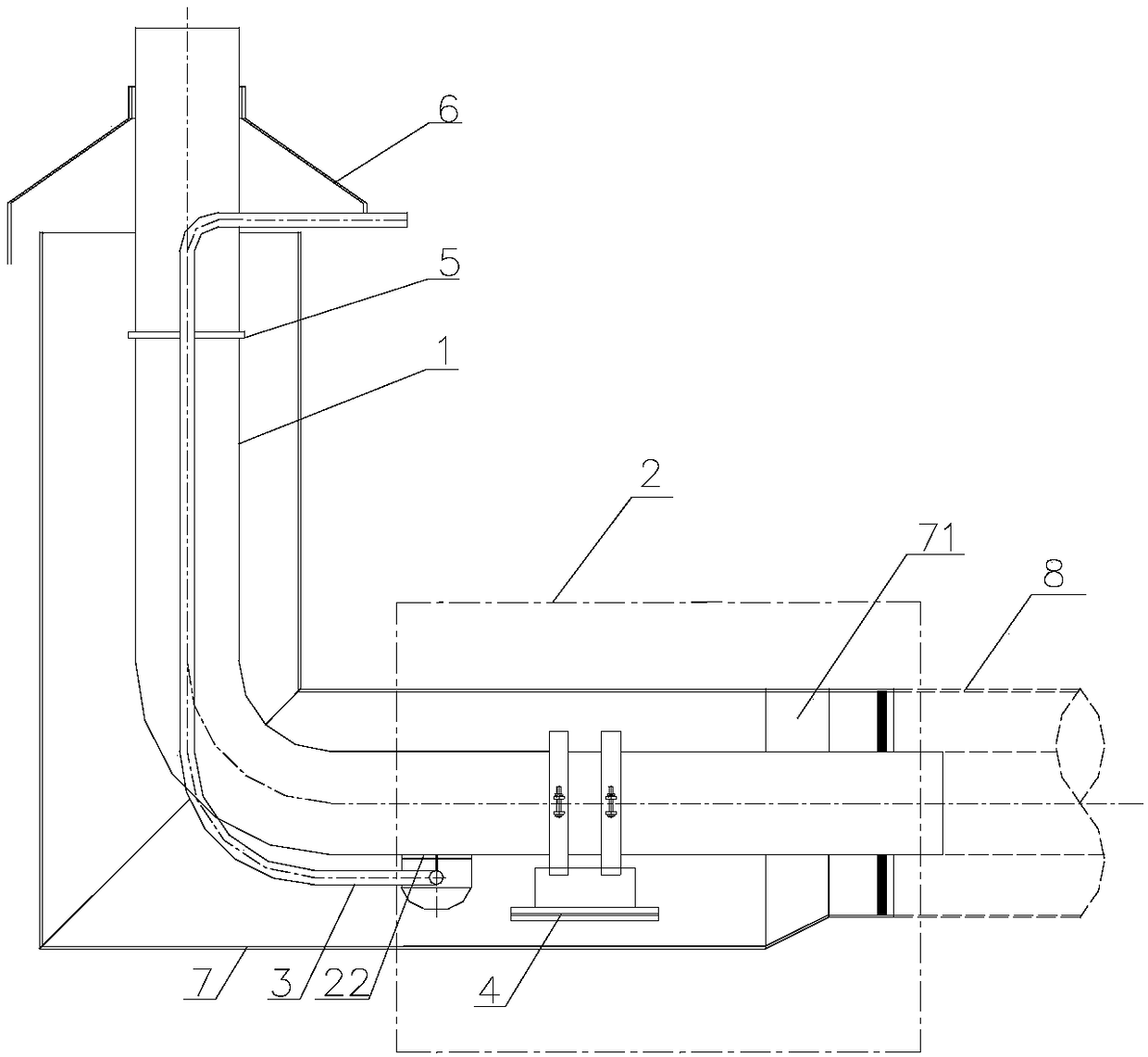
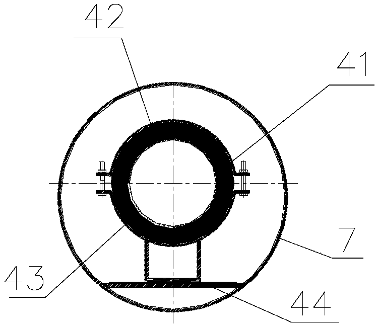
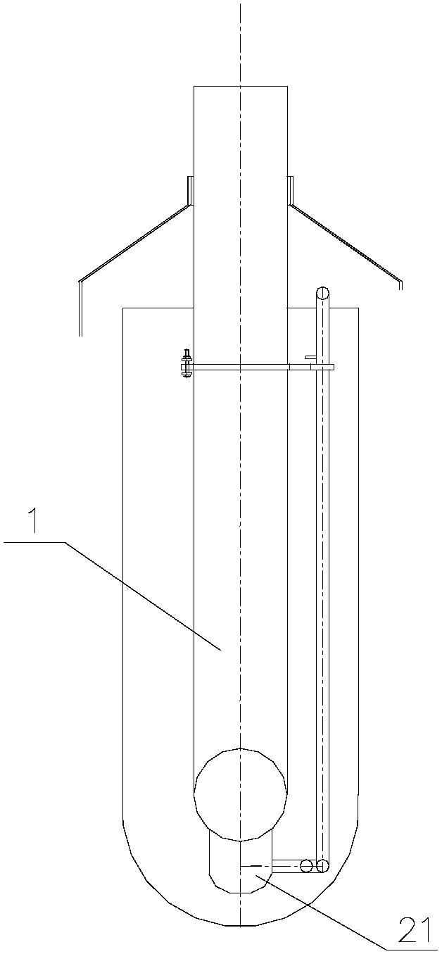
[0026] Such as figure 1 , image 3 As shown, a steel-sleeved steel elbow drainage structure connecting directly buried and overhead steam pipelines includes:

[0027] The diameter-expanding standpipe part is composed of the riser of the "L"-shaped diameter-expanding outer protection pipe 7 and the long-arm elbow 1 arranged inside the riser ...


PUM


Abstract

The invention provides a steel jacket steel bent pipe dewatering structure for connecting direct burial and overhead steam pipes. The structure comprises a diameter expansion stand pipe part, a diameter expansion dewatering part, a dewatering long bent pipe and a reducing pipe, wherein a stand pipe of an L-shaped diameter expansion outer protecting pipe and a long arm bent pipe arranged in the stand pipe form a steel jacket steel structure; a rainproof cap is arranged in the connected position of the ground of the long arm bent pipe with an overhead section; a direct burial pipe of the L-shaped diameter expansion outer protecting pipe and a working pipe arranged in the direct burial pipe form a steel jacket steel structure; the diameter expansion stand pipe part and the diameter expansiondewatering part are connected in an equal-diameter manner; the dewatering long bent pipe consists of a large-curvature long arm dewatering pipe and a support limiting ring; and the reducing pipe is used for connecting the diameter expansion dewatering part with a standard caliber outer protecting pipe. The structure is reasonable in design, reduces the mounting investment, improves the mounting efficiency, maximizes natural compensation effect on a Z-shaped bent pipe, and solves the problems of thermal expansion displacement, low-frequency vibration and the like in a long dewatering pipe.

Description

technical field [0001] The invention relates to the field of directly buried steam heat preservation pipelines, in particular to a structure for solving overhead steam heat preservation pipelines, directly buried compensation connections and low-point drainage, that is, a steel-sleeved steel elbow pipe drainage for connecting directly buried and overhead steam pipelines structure. Background technique [0002] When the steam insulation pipeline is changed from underground direct burial to overhead laying on the ground, a relatively low water level is formed at the corner of the direct burial elevation, and the condensed water generated by the temperature difference in the working pipe gathers at the corner due to the action of gravity. This situation usually occurs in the nearest Set drainage and drainage devices, otherwise water hammer will easily cause damage to the pipeline, and since structures similar to drainage joints include water collection tanks, drainage pipes and...

Claims


Application Information

Patent Timeline
IPC IPC(8): F16L55/07F16L43/00F16L59/22F16L51/04
CPCF16L43/00F16L51/04F16L55/07F16L59/22
Inventor 王庆博李晓敏
Owner CHINA DALIAN KEHUA HEATING PIPE
Learn More