
Electronic lock handle with inbuilt clutch

A clutch and lock handle technology, which is applied to the spherical handle of the wing fan, the handle connection, the wing fan handle, etc., can solve the problems of increasing the production cost of electronic locks, reducing the adaptability range of the lock body, and increasing the cost of the lock body. Promotional use, simple structure, scientific and reasonable design

Pending Publication Date: 2018-09-28
北京洛克欧乐科技有限公司
View PDF6 Cites 11 Cited by
  • Summary
  • Abstract
  • Description
  • Claims
  • Application Information

AI Technical Summary

Problems solved by technology

In the existing market, mechanical locks account for the vast majority, and electronic locks are only applicable to the field of electronic locks, which leads to an increase in the production cost of electronic locks. Users must purchase electronic locks that are more expensive than mechanical locks while purchasing electronic locks. body
It can be seen that building the clutch into the lock body will directly lead to an increase in the cost of the lock body and reduce the adaptation range of the lock body

Method used


Image

  • Electronic lock handle with inbuilt clutch
  • Electronic lock handle with inbuilt clutch
  • Electronic lock handle with inbuilt clutch

Examples


Embodiment Construction

[0018] In order to make the purpose, technical solutions and advantages of the embodiments of the present invention clearer, the technical solutions in the embodiments of the present invention will be clearly and completely described below in conjunction with the drawings in the embodiments of the present invention.

[0019] Embodiments of the present invention are described in detail below, and examples of the embodiments are shown in the drawings, wherein the same or similar reference numerals denote the same or similar elements or elements having the same or similar functions throughout. The embodiments described below by referring to the figures are exemplary and are intended to explain the present invention and should not be construed as limiting the present invention.

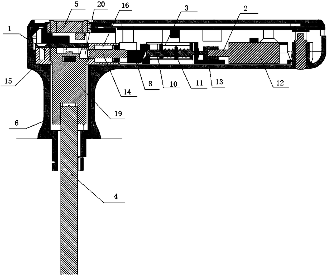
[0020] The present invention proposes an electronic lock handle with a built-in clutch, such as figure 1 As shown, it includes a clutch 1 built in the outdoor handle, a driving device 2, a transmission de...


PUM


Abstract

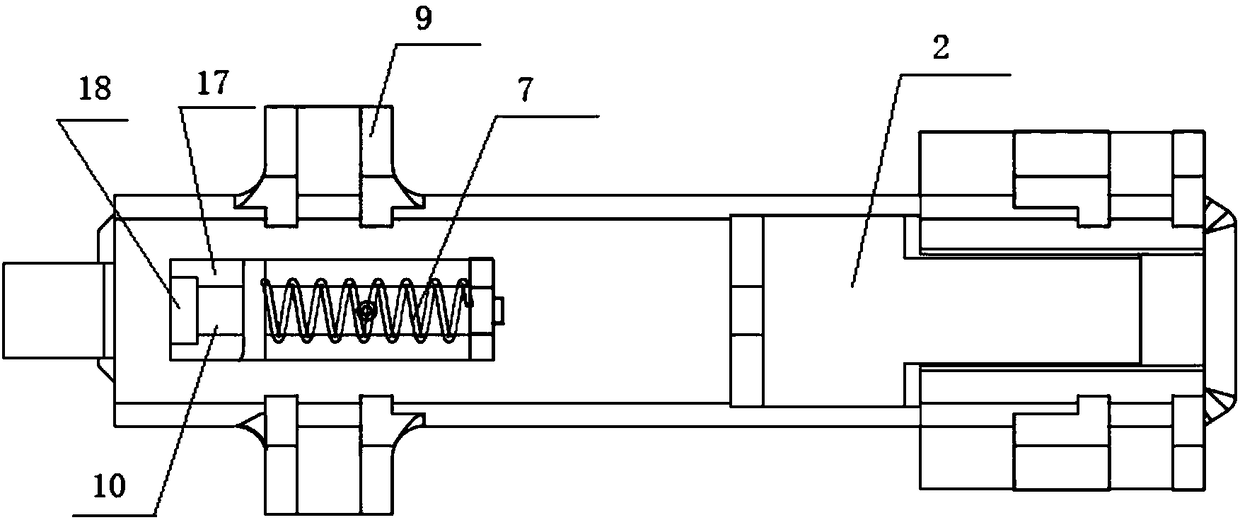
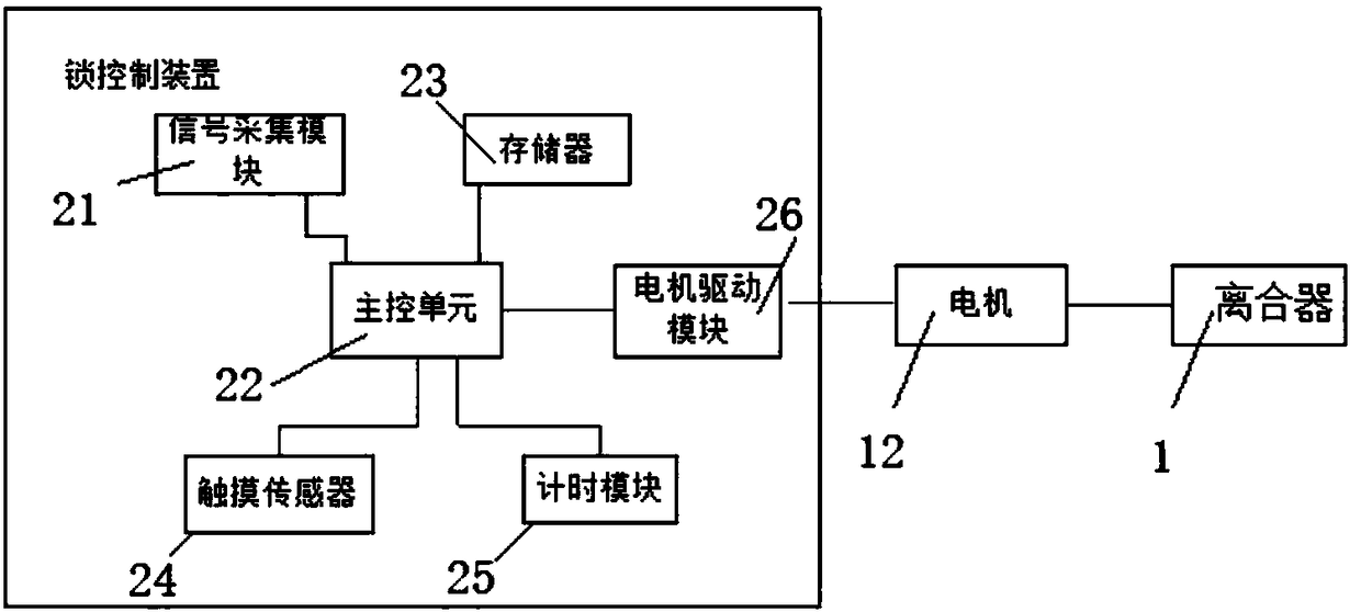
The invention discloses an electronic lock handle with an inbuilt clutch. The electronic lock handle comprises the clutch, a driving device, a transmission device, square steel, a lock control deviceand a handle body, wherein the clutch is arranged in an outdoor handle in an inbuilt manner; the transmission device comprises a transmission spring, a dissociative piece fixing piece and a driving rod; the transmission spring is fixedly connected with a dissociative piece; the driving device is fixedly connected with the driving rod; the spiral coil of the transmission spring is embedded on the driving rod in a sleeving manner; a fixing pin penetrating through the spiral coil of the transmission spring in an inserted manner is arranged on the driving rod; opening and closing of the clutch arecontrolled through triggering of the dissociative piece; and the clutch is arranged in the handle body to control connection and separation of the handle body and square steel. The electronic lock handle is simple in structure and high in practicality and increases the application range of the lock.

Description

technical field [0001] The invention relates to the field of mechanical structures, in particular to an electronic lock handle with a built-in clutch. Background technique [0002] At present, the technical solutions adopted by most electronic locks on the market are to design the clutch in the outdoor panel of the electronic lock, or to build the electronic lock clutch into the lock body, and the electronic lock manufacturers directly purchase the electronic lock body with the built-in clutch to realize the electronic lock. enabled features. In the existing market, mechanical locks account for the vast majority, and electronic locks are only applicable to the field of electronic locks, which leads to an increase in the production cost of electronic locks. Users must purchase electronic locks that are more expensive than mechanical locks while purchasing electronic locks. body. It can be seen that building the clutch into the lock body will directly lead to an increase in ...

Claims


Application Information

Patent Timeline
Patent Type & Authority Applications(China)
IPC IPC(8): E05B1/00E05B3/00E05B47/00E05B15/00G07C9/00
CPCG07C9/00563E05B1/003E05B3/003E05B15/0013E05B47/0012E05B2047/0014
Inventor 张继学蔡靖
Owner 北京洛克欧乐科技有限公司
Learn More