Direction change driven slide block mechanism
A driving type and slider technology, which is applied in the field of direction-changing driven slider mechanism, can solve the problems of inconvenient assembly, complicated installation and processing of oblique mechanism, etc., and achieve the effect of convenient installation, small strength damage and reliable mechanism action
- Summary
- Abstract
- Description
- Claims
- Application Information
AI Technical Summary
Problems solved by technology
Method used
Image
Examples
Embodiment Construction
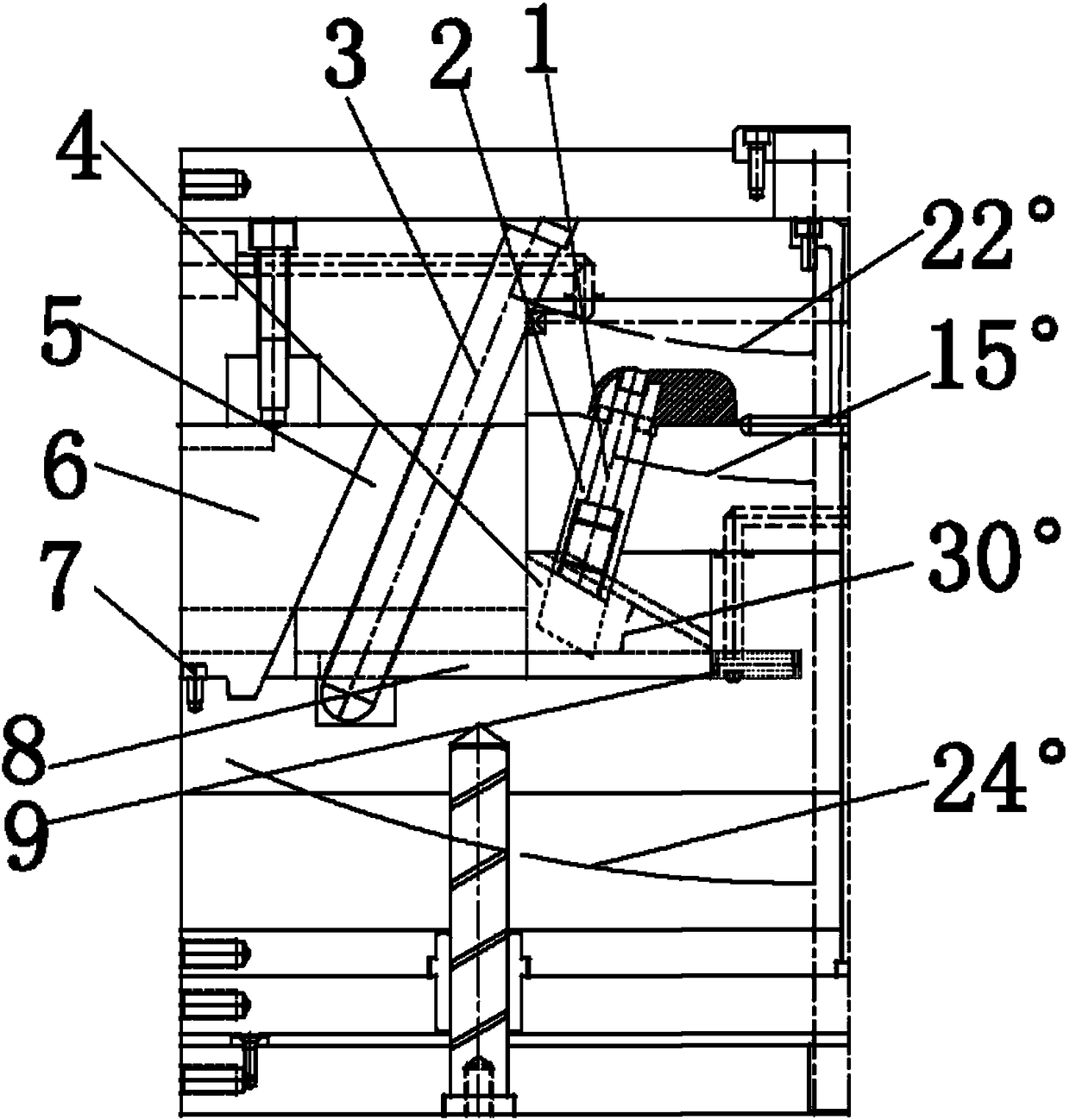
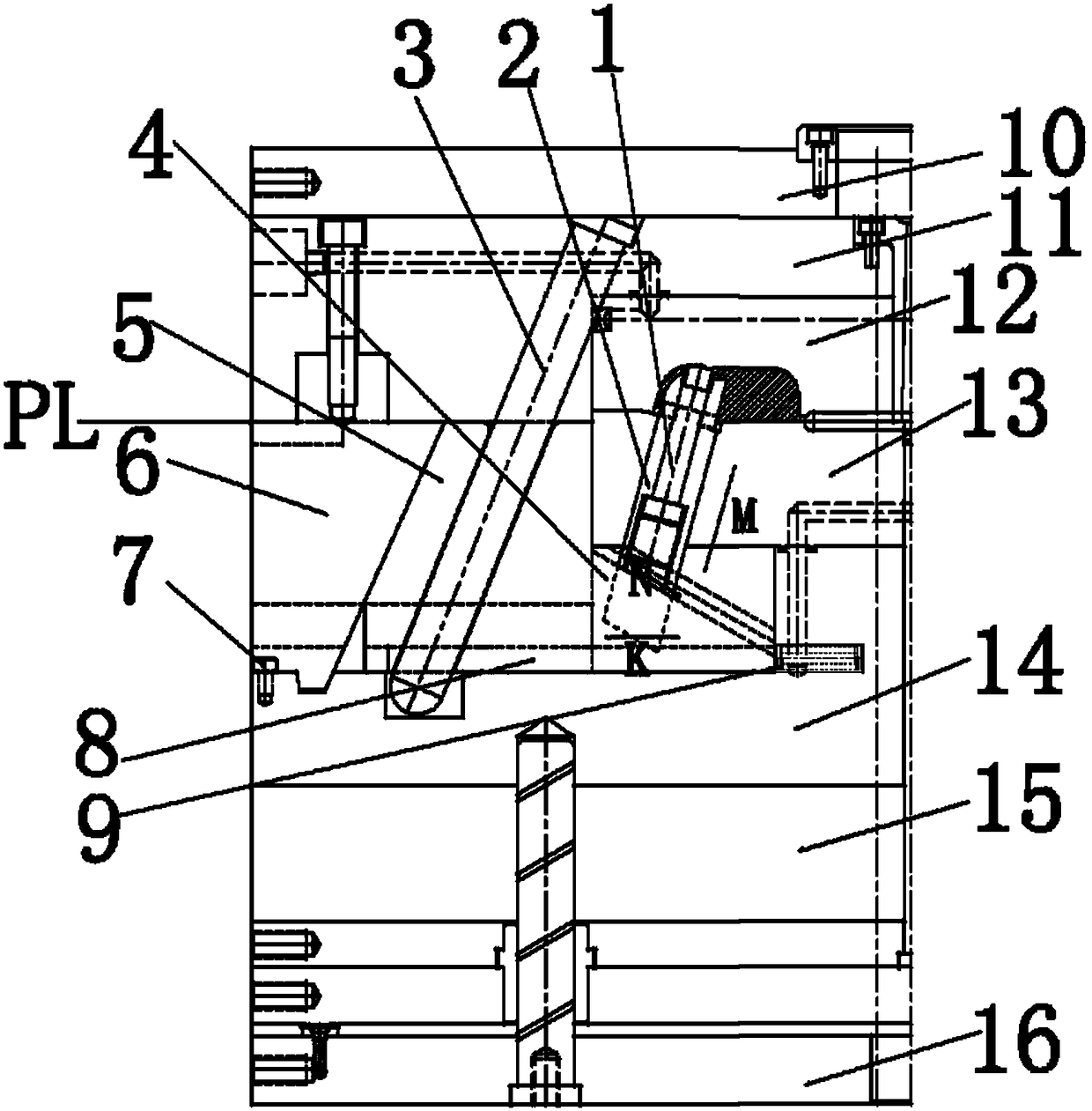
[0015] Figure 1-2 Shown is the relevant explanatory figure of the present invention; The specific embodiment is, as figure 1 , figure 2 As shown, a direction-changing driven slider mechanism includes an oblique needle 1, an oblique core 2, an oblique guide post 3, a belt-driven T-slot slider head 4, a main slider body 5, and a main slider Lock block 6, main slider limit screw 7, main slider bezel 8, main slider driving spring 9.
[0016] The mold structure of the application object of the mechanism includes a fixed mold panel 10 , a fixed template 11 , a cavity insert 12 , a core insert 13 , a movable template 14 , an ejector plate spacer 15 , and a movable mold bottom plate 16 .
[0017] In the mechanism, the oblique needle 1 is installed on the oblique core 2, together with the oblique core 2, it forms the molded part of the oblique hole on one side of the moving mold of the product; the tail end of the oblique core 2 is designed with a T-shaped Slot head, through the T...
PUM
 Abstract
Description
Claims
Application Information
 - Generate Ideas
- Intellectual Property
- Life Sciences
- Materials
- Tech Scout
- Unparalleled Data Quality
- Higher Quality Content
- 60% Fewer Hallucinations
Browse by: Latest US Patents, China's latest patents, Technical Efficacy Thesaurus, Application Domain, Technology Topic, Popular Technical Reports.
© 2025 PatSnap. All rights reserved.Legal|Privacy policy|Modern Slavery Act Transparency Statement|Sitemap|About US| Contact US: help@patsnap.com


