A manipulator fixed adjustment table

A technology of adjusting table and manipulator, applied in the field of manipulator, can solve the problem that the stability of manipulator cannot be well guaranteed, and achieve the effect of convenient adjustment and increase of rolling effect.

Active Publication Date: 2021-02-19
广东聚晨知识产权代理有限公司
View PDF7 Cites 1 Cited by
  • Summary
  • Abstract
  • Description
  • Claims
  • Application Information

AI Technical Summary

Problems solved by technology

[0002] The manipulator is a tool that is more convenient to carry and grab objects among the tools. When fixing the manipulator, the manipulator is mainly fixed on the placement table, and the manipulator is fixed by inserting the screw into the screw hole, which is not very good. Ensure the stability of the manipulator

Method used


Image

  • A manipulator fixed adjustment table
  • A manipulator fixed adjustment table
  • A manipulator fixed adjustment table

Examples


Embodiment 1

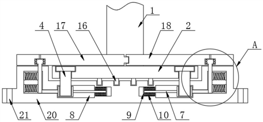
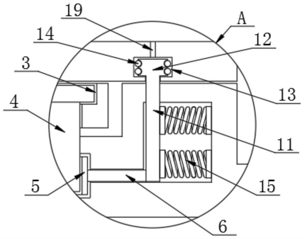
[0022] The present invention provides such Figure 1-3 A manipulator fixed adjustment table shown includes a vertical rod 1, the bottom of the vertical rod 1 is provided with a placement plate 2, the surface of the placement board 2 is provided with a screw hole 3, and the inner wall of the screw hole 3 is provided with a screw rod 4, The bottom of the screw rod 4 is provided with a movable nut 5, one end of the movable nut 5 is provided with a first rope 6, the other side of the movable nut 5 is provided with a second rope 7, and the outer side of the movable nut 5 is provided with a second rope 7. There is a movable groove 8, one end of the second rope 7 is provided with a supporting plate 9, one side of the supporting plate 9 is provided with a first spring 10, one end of the first rope 6 is provided with a movable plate 11, and the movable plate 11 The top is provided with a ring block 12, the outer side of the ring block 12 is provided with an oil groove 13, the surface o...

Embodiment 2

[0025] The bottom end of the vertical rod 1 is fixedly connected with the placing plate 2, and the placing plate 2 matches the fixing plate 20, which is convenient for fixing the placing plate 2, thereby increasing the stabilizing effect when the manipulator works.

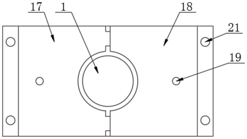
[0026] One side of the first rotating plate 17 is provided with a protruding rod, and one side of the second rotating plate 18 is provided with a groove, the protruding rod matches the groove, and the arc groove corresponds to the vertical rod 1 The first rotating plate 17 and the second rotating plate 18 are covered on the top of the placing plate 2 by means of groove buckling, further fixing the placing plate 2 .

[0027] The inner top surface of the fixed plate 20 is provided with a buckle groove, and the buckle groove is matched with the protrusion 16 to increase the fastening effect of the placement plate 2 and prevent the relative rotation of the placement plate 2 inside the fixed plate 20. 16 is fixedly con...


PUM


Abstract

The invention discloses a manipulator fixed adjusting table. The manipulator fixed adjusting table comprises a stand rod; a placing plate is arranged at the bottom of the stand rod; a screw hole is formed in the surface of the placing plate; a screw rod is arranged on the inner wall of the screw hole; a movable screw cap is arranged at the bottom of the screw rod; a first rope is arranged at one end of the movable screw cap; a second rope is arranged on the other side of the movable screw cap; a movable groove is formed in the outer side of the movable screw cap; a support plate is arranged atone end of the second rope; a first spring is arranged on one side of the support plate; a movable plate is arranged at one end of the first rope; a ring block is arranged at the top of the movable plate; and an oil tank is formed in the outer side of the ring block. Through arrangement of the ring block, lubricating oil is added in the oil tank through an oil hole; then, a first rotating plate is pulled to drive the movable plate to extrude a second spring; the first rotating plate is rotated by 180 degrees with the ring block as axis; similarly, a second rotating plate is equally operated;and then, the screw rod is deviated from the screw hole and the movable screw cap, and the placing plate is taken out from a fixed plate.

Description

technical field [0001] The invention relates to the technical field of manipulators, in particular to a fixed adjustment table for manipulators. Background technique [0002] The manipulator is a tool that is more convenient to carry and grab objects among the tools. When fixing the manipulator, the manipulator is mainly fixed on the placement table, and the manipulator is fixed by inserting the screw into the screw hole, which is not very good. Ensure the stability of the manipulator. [0003] Therefore, it is necessary to invent a manipulator fixed adjustment table to solve the above problems. Contents of the invention [0004] The purpose of the present invention is to provide a manipulator fixed adjustment table, add lubricating oil to the inside of the oil groove through the oil hole, increase the rolling effect of the ball, and then pull the first rotating plate, the first rotating plate drives the movable plate to squeeze the second spring , the first rope is stre...

Claims


Application Information

Patent Timeline
Patent Type & Authority Patents(China)
IPC IPC(8): B25J9/00
CPCB25J9/0009
Inventor 陈保锋
Owner 广东聚晨知识产权代理有限公司
Why Eureka
Try Eureka