Reel front cleaning mopping machine

A technology of mopping machine and cleaning mechanism, which is applied in the direction of cleaning carpets, cleaning machinery, cleaning floors, etc., can solve the problems of complicated movement of clamping arms and jaws, disturbing the driver's sight, uneven cleaning, etc., to improve the quality of mopping and cleaning. , Improve work efficiency and facilitate cleaning

Active Publication Date: 2020-02-28
SUINING CHANGFENG MECHANICAL TECH
View PDF6 Cites 0 Cited by
  • Summary
  • Abstract
  • Description
  • Claims
  • Application Information

AI Technical Summary

Problems solved by technology

However, the above mopping machines all have these common defects: 1. The cleaning pool is too long, longer than mopping handkerchiefs, and takes up too much space
2. The agitating bar rotates around the axis in an arc-shaped agitation. When agitating the handkerchief, a considerable part of the middle of the handkerchief in the arc cannot be agitated, and the cleaning is uneven.
4. The handkerchief is lifted from the ground and transferred to the upper mouth of the cleaning pool before it can be put into the cleaning pool. It needs to be transferred with the clamp arm and claw. The movement of the clamp arm and claw is complicated and the swing space is large.
Because the jaws of the clamp arm rotate up and down and left and right in front of the car body, it seriously interferes with the driver's sight

Method used


Image

  • Reel front cleaning mopping machine
  • Reel front cleaning mopping machine
  • Reel front cleaning mopping machine

Examples


Embodiment Construction

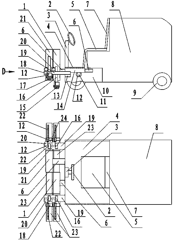
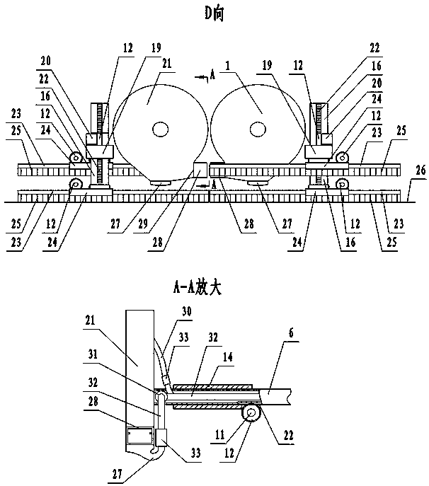
[0020] figure 1 In the middle is the overall structure diagram of the reel pre-cleaning and mopping machine. The upper picture is the front view, and the lower picture is the top view. figure 2 in, yes figure 1 D direction diagram. Two sets of mopping handkerchiefs are installed side by side on the front left and right of the car body of the reel front cleaning and mopping machine, each set of two handkerchiefs, and the left handkerchiefs on the left side of the car body, namely the two handkerchiefs below the picture below, are called the left handkerchief group , the two handkerchiefs on the right side of the car body are called the right handkerchief group. A broom handle 16 is all connected above every mopping handkerchief.

[0021] A broom handle frame 19 is respectively installed on the pedal 4 bottom left and right of the car body, and the broom handle frame 19 right sides are fixed on the frame 13 below the pedal on the car body. The broom handles connected above...


PUM


Abstract

Reel front cleaning and mopping machine, including telescopic arm, mop, broom handle lifting mechanism, cleaning mechanism, tank shell mechanism, and car body. Two cleaning mechanisms are installed horizontally in front of the car body, and two groups of mopping handkerchiefs are installed below the cleaning mechanism, and each group has two rows of mopping handkerchiefs. A rotating wheel, a swivel ring, a swivel ring sleeve and a stirring washing plate are installed in the stirring washing shell of the cleaning mechanism. Hanging cards and push cards are installed on the swivel. The handkerchief strips are connected under the base sheet. There are slides on both sides of the plate frame of the mop and the outer circle of the runner, and the substrate is inserted into the slides. Front and rear mopping handcarts take turns mopping and cleaning. The hanger on the swivel pulls the dirty mopping base sheet out of the slideway of the mopping rack and into the runner slideway in the agitating shell. The rotary ring stirs and dehydrates the handkerchief strips in the stirring shell, and then the rotary ring reverses to insert the clean substrate into the rack again. Because the mopping handkerchief is cleaned with the vehicle, the mopping floor is cleaner, the width of the mopping floor can be increased, and the work efficiency is greatly improved. It is suitable for quick scrubbing in stations, subways, tunnels, squares, and public places.

Description

technical field [0001] The invention belongs to the field of environmental protection machinery, in particular to a reel pre-cleaning and mopping machine. Background technique [0002] The present elongated frame-type mopping handkerchief is a widely used tool for mopping the floor. Especially in residential quarters, shopping malls, office spaces, schools, hospitals, most of the cleaners mop the floor with the elongated plate frame mopping handkerchief to wipe the floor. The cleaning of this strip-shaped mop has been a troublesome thing for a long time. One is that the mop is too long. If there is no special rectangular cleaning pool, the general basin cannot fit it. Flushing with tap water is a waste of water and not clean. Moreover, dehydration after washing is also very troublesome, and the dehydration effect is very poor. Workers dripping water while walking with a mop. Mopping machine capable of automatically cleaning mop, patent application number: 2017107145490;...

Claims


Application Information

Patent Timeline
Patent Type & Authority Patents(China)
IPC IPC(8): A47L11/30A47L11/40
CPCA47L11/30A47L11/40A47L11/4016A47L11/4027
Inventor 邹家鸿邹家福张文彬邹永平邹家华胡冬梅
Owner SUINING CHANGFENG MECHANICAL TECH
Why Eureka
Try Eureka