Multi-direction buckle device

A technology of male and female buckles, applied in belt buckles, fasteners, clothing, etc., can solve problems such as simultaneous release of male buckles

Inactive Publication Date: 2018-09-28
LIAN YANG PLASTIC (SHEN ZHEN) CO LTD
View PDF4 Cites 3 Cited by
  • Summary
  • Abstract
  • Description
  • Claims
  • Application Information

AI Technical Summary

Problems solved by technology

However, due to the internal structure of the existing multi-directional buckle, all the male buckles can only be released at the same time by pressing the central part of the button. Buckle, therefore, its operational convenience needs to be strengthened

Method used


Image

  • Multi-direction buckle device
  • Multi-direction buckle device
  • Multi-direction buckle device

Examples


Embodiment 1

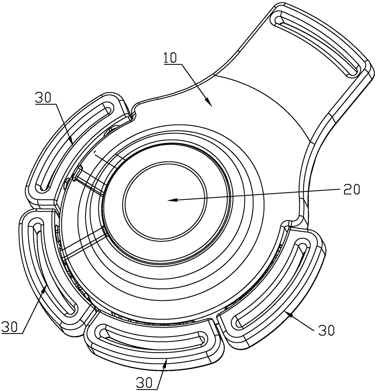
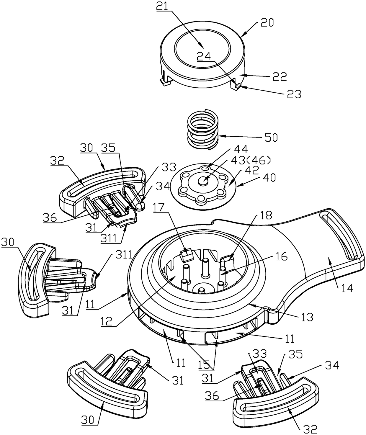
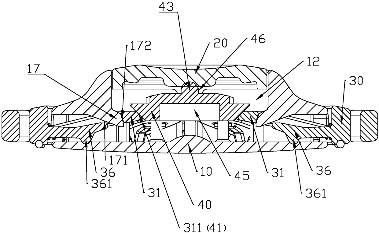
[0032] like Figure 1 ~ Figure 3 As shown, the multi-directional buckle device of this embodiment includes a female buckle body 10 , a button 20 , a male buckle 30 , a force transmission member 40 , and a reset elastic member 50 .

[0033] like figure 2 , Image 6 , Figure 7 , Figure 8 As shown, the female buckle body 10 is provided with a plurality of slots 11 into which the male buckle 30 can be movably inserted and a key slot 12 for accommodating the key 20 . The male buckles 30 can be respectively inserted into the card slots 11 to lock and connect with the female buckle body 10, and the buttons 20 are arranged in the button grooves 12, which are used for pressing to unlock; The force transmission member 40 is arranged between the button 20 and the pressing end 31 of the male button 30, and it is used to distribute the force of the button 20 to each male button 30 evenly, so that each male button 30 can be connected with the male button 30 at the same time. The fem...

Embodiment 2

[0054] like Figure 4 , Figure 5 As shown, the multi-directional buckle device of this embodiment includes a female buckle body 10 , a button 20 , a male buckle 30 and a force transmission member 40 .

[0055] The structures of the button 20 and the male buckle 30 are the same as in the first embodiment.

[0056] like Figure 5 As shown, the structure of the female button body 10 is basically the same as that of Embodiment 1, the difference is that a limiting post 16 is set in the button groove 12 of the female button body 10 in Embodiment 1, and in this embodiment, the button A supporting portion 19 is provided in the slot 12 to replace the limiting post 16 . The supporting portion 19 is enclosed in a circular shape, which can stably support the sphere.

[0057] In this example, if Figure 4 , Figure 5 As shown, the force transmitting member 40 is in the shape of a sphere, and its spherical surface forms the pressing surface 41 and the force bearing surface 46 . Simi...


PUM


Abstract

A multi-direction buckle device comprises a female button body, keys, a plurality of male buttons, and a power transmission part. The female button body is provided with a plurality of clamping slotsand key slots. The clamping slot is provided with a first positioning part. A key is arranged in each key slot and can be pressed relative to the female button body. The plurality of male buttons areprovided with a connecting end and a compression end for connecting external connectors, respectively. The compression end is provided with a second positioning part that can cooperate with a first positioning part. When the male button is inserted in the clamping slot, the cooperation between the first positioning part and the second positioning part makes the male button limited in the clampingslot, so that the male button can not eject actively. The power transmission part is arranged between the key and the compression end of the male button, and provided with a compression surface that can simultaneously act with the compression ends of the plurality of mal buttons and a carrying surface that can receive the key pressure from multiple directions, when any position of the button is pressed, all of the carrying surfaces of the power transmission part can receive the pressure of buttons to make the compression surface simultaneously compress the compression ends of all the male buttons and make the second positioning part and the first positioning part separated, so that all the male buttons are simultaneously separated from the female button body.

Description

【Technical field】 [0001] The invention relates to a buckle, in particular to a multi-directional buckle device. 【Background technique】 [0002] As a connector, the buckle is widely used in a variety of products, such as bags, child safety seats, and strollers. Especially in child safety seats and strollers, when multi-directional fixation is required, multi-directional buckles will be used: the female buckle body can be plugged with multiple male buckles, so that it can be used to fix in multiple directions safety belt for secure connection. The existing multi-directional buckle can usually be unlocked by pressing the button in the middle. When unlocking, all the male buckles can be released simultaneously and taken out. However, due to the internal structure of the existing multi-directional buckle, all the male buckles can only be released at the same time by pressing the central part of the button. Buckle, therefore, its operational convenience still needs to be streng...

Claims


Application Information

Patent Timeline
IPC IPC(8): A44B11/25
CPCA44B11/2511
Inventor 李邱宗
Owner LIAN YANG PLASTIC (SHEN ZHEN) CO LTD
Why Eureka
Try Eureka