
Storing and fixing device for dynamic electrocardiograph

A dynamic electrocardiogram and fixing device technology, which is applied in the fields of caps with auxiliary devices, sealing parts with auxiliary devices, medical science, etc., can solve the problems of inconvenient storage and easy entanglement of lead wires, etc., and achieve strong storage capacity, Good safety and anti-shaking effect

Inactive Publication Date: 2018-09-25
隋红
View PDF0 Cites 3 Cited by
  • Summary
  • Abstract
  • Description
  • Claims
  • Application Information

AI Technical Summary

Problems solved by technology

Since the lead wire is easy to be entangled, it is inconvenient to store after use

Method used


Image

  • Storing and fixing device for dynamic electrocardiograph
  • Storing and fixing device for dynamic electrocardiograph
  • Storing and fixing device for dynamic electrocardiograph

Examples


example 1

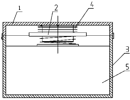
[0016] As shown in Figure 1 and Figure 2, this specific embodiment includes a wire winder 2, a box body 3 and a box cover 1, one side of the box cover 1 and one side of the box body 3 are connected by a hinge, the box cover 1 and the box body The other side of 3 is provided with a first locking mechanism.

[0017] As shown in Fig. 4, Fig. 5 and Fig. 6, the wire winder 2 includes a storage cylinder 21, a turntable 22, a pressure plate 24, a spring 23 and a sliding disk 26, the storage cylinder 21 includes a cylindrical shell and a bottom plate, and the bottom plate is fixed on the cylindrical shell The lower end of the body, one side of the upper end of the cylindrical shell is hinged with the inner surface of the box cover 1, and a second locking mechanism is arranged between the other side of the upper end of the cylindrical shell and the box cover 1, and a The length direction is the linear chute 211 in the axial direction of the cylindrical shell. The lower end of the linea...

example 2

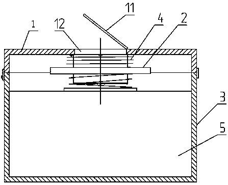
[0020] As shown in Figure 3, the difference between this specific embodiment and Example 1 is that: the tank cover 1 is provided with a storage hole 12 communicating with the cylindrical shell, the tank cover 1 is hinged with a cylinder cover 11, and the cylinder cover 11 and the tank cover 1 A third locking mechanism is arranged between them (not shown in the figure, the three locking mechanisms in this specific embodiment can all adopt conventional locking mechanisms), and when the third locking mechanism is locked, the cylinder cover 11 covers Live in storage hole 12.

[0021] In this specific embodiment, the tube cover 11 can be opened outside the box cover 1 , so that other items can be stored in the storage tube 21 .


PUM


Abstract

The invention discloses a storing and fixing device for a dynamic electrocardiograph. A winder of the storing and fixing device comprises a storage cylinder, a rotating disc, a pressure disc, a springand a sliding disc, wherein the sliding disc sleeves on a cylinder shell and is arranged in a linear sliding chute in a sliding manner; the pressure disc is arranged below the sliding disc; the spring sleeves on the cylinder shell and is connected with the sliding disc and the pressure disc; the rotating disc is rotatably arranged on the cylinder shell in an axial movement manner and is located above the sliding disc; a groove which runs through the outer side wall in the cylinder shell is formed in the upper end surface of the cylinder shell; and a clamping slot is formed in the rotating disc and comprises a round hole and threading slots, the round hole runs through the rotating disc along the axial direction, the threading slots run through the upper and lower side surfaces and side wall of the rotating disc and are communicated with the round hole, and the width of the threading slots is smaller than the outer diameter of the round hole. The storing and fixing device is strong instorage capacity; and when the device is covered with a tank cover, the spring can compress guiding linkage wires and a host, so that the situation that the host and the guiding linkage wires are shaken in the tank body can be prevented, and the safety is good.

Description

technical field [0001] The invention relates to a medical instrument storage device, in particular to a dynamic electrocardiograph storage and fixing device. Background technique [0002] A dynamic electrocardiograph is an instrument for routine medical examination. The existing dynamic electrocardiograph includes an electrocardiometer host and several lead wires, and each lead wire is connected to the electrocardiometer host and detection electrodes. The lead wire can be removed from the main body of the electrocardiograph. One end of the lead wire is a plug and the other end is an electrode, and the middle is a thin wire. All lead wires share a single plug. Since the lead wire is easy to be entangled, it is inconvenient to store after use. Contents of the invention [0003] The technical problem to be solved by the present invention is to provide a dynamic electrocardiograph storage and fixing device which is convenient for storing the dynamic electrocardiograph. [0...

Claims


Application Information

Patent Timeline
Patent Type & Authority Applications(China)
IPC IPC(8): B65D51/24B65D51/28A61B50/30
CPCB65D51/24A61B50/30A61B2050/0051A61B2050/0067B65D51/28
Inventor 隋红
Owner 隋红
Learn More