


Quick Research
Generate reliable direction feasibility study reports for your R&D in just a few steps.

Technical Q&A
Discover and master advanced knowledge NOW. Basics, ideas, possibilities, all at once.

Find Solutions
As an expert in R&D theories, this can generate solutions to your technical problems instantly.

Evaluate Feasibility
Analyze your overall solution with one click, know your potential R&D risks in advance.

Monitor Landscape
Get weekly tech updates, stay abreast of the latest tech innovations and key insights.
a floating breakwater
A technology of floating breakwaters and floating tanks, which is applied in the field of marine engineering to achieve the effect of high flexibility and low cost
- Summary
- Abstract
- Description
- Claims
- Application Information
AI Technical Summary
Problems solved by technology
Method used
Image

Examples
Embodiment 1
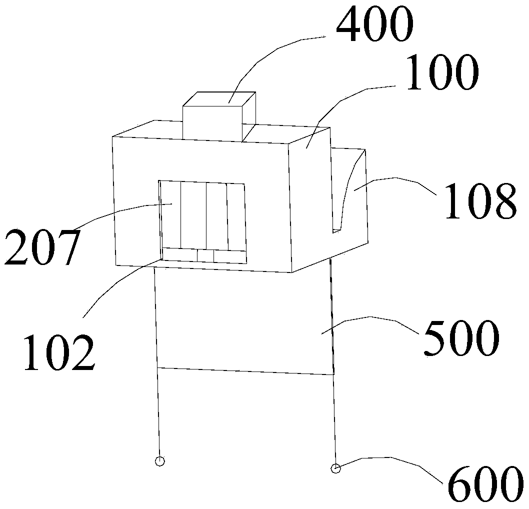
[0043] see figure 1 and Figure 4 As shown, this embodiment provides a floating breakwater, including: several connected buoyant tanks 100 and an energy conversion mechanism arranged on the buoyant tanks 100 .
[0044] The buoy 100 includes a hollow receiving cavity, an opening 102 suitable for passage of seawater is provided on the facing side of the receiving cavity, and a hollow wave-dissipating component is provided at the other end of the receiving cavity corresponding to the opening 102 . The buoyancy tank 100 is connected with the anchor block on the seabed through anchor chains.
[0045] The wave-dissipating assembly includes several parallel-arranged wave-dissipating plates 105; the wave-dissipating plates 105 are uniformly provided with several hollow wave-dissipating holes 106.
[0046] In order to further improve the anti-wave function of the floating breakwater of this embodiment, the buoyancy tank 100 is also integrally provided with a wave-proof plate 108 faci...
Embodiment 2
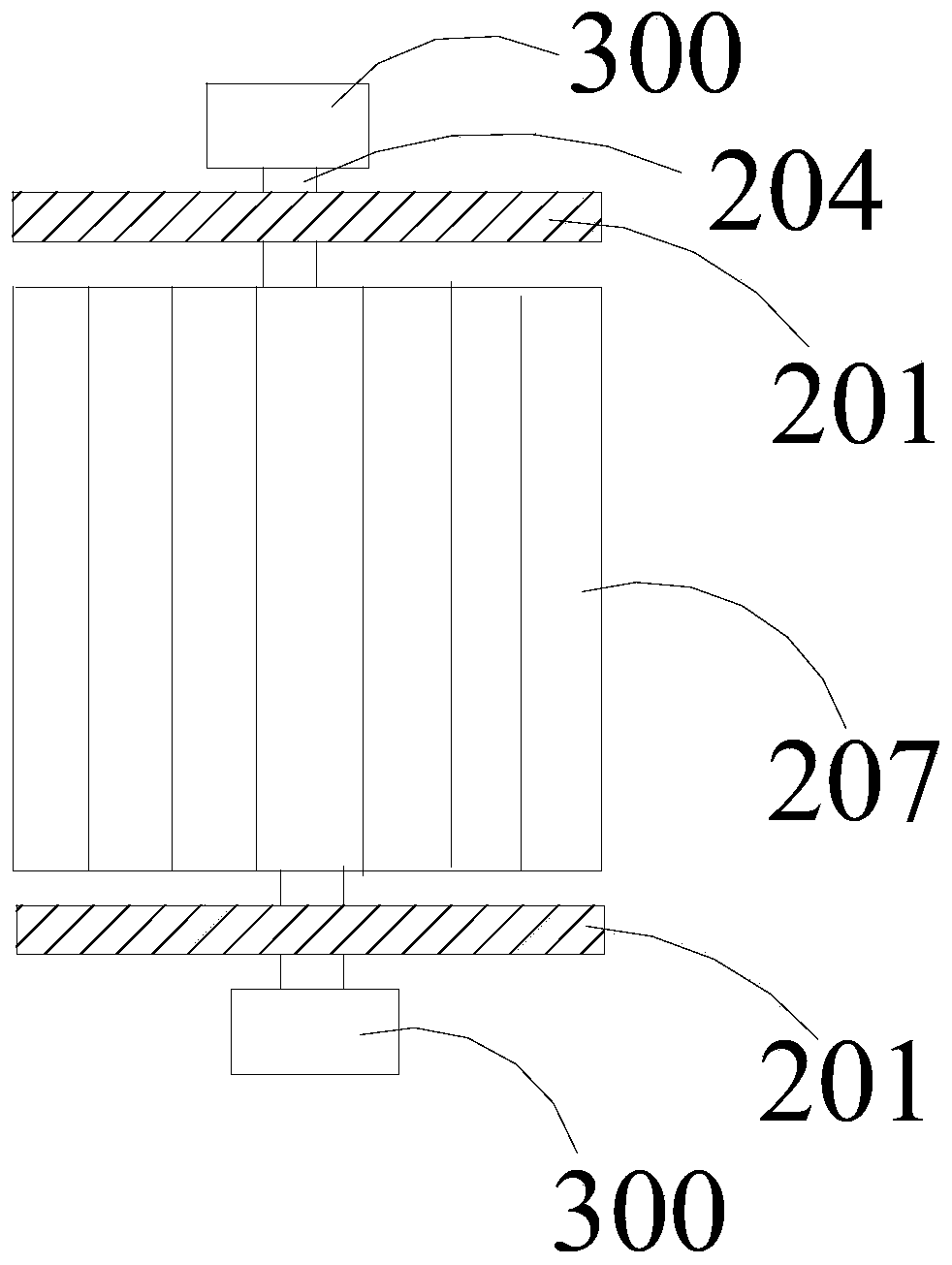
[0056] see Figure 6 As shown, on the basis of the floating breakwater of embodiment 1, the left and right side walls of the buoyancy tank 100 of the floating breakwater of the present embodiment are also provided with side openings 103 suitable for the passage of water. The benefits of this design That is, when waves of different directions attack the buoyant tank 100 , the rotating blades 207 on the rotating shaft 204 can sense the waves in different directions through the opening 102 or the side opening 103 on the buoyant tank 100 to produce a rotation effect.
Embodiment 3
[0058] see Figure 4 As shown, on the basis of the floating breakwater of embodiment 1 or embodiment 2, the bottom of the buoyancy tank 100 of the floating breakwater of the present embodiment is rigidly connected with some rows of net clothing 500; Setting; a number of mesh holes 504 are evenly arranged on the netting 500; sinkers 600 are arranged at the bottom of the netting 500. Some rows of net clothes 500 can be optionally set as three rows of net clothes 500 . Because the draft of the buoyancy tank 100 of the floating breakwater is relatively shallow under the effect of buoyancy, it is difficult to ensure that the invasion of underwater waves can definitely drive the rotation of the rotating blade 207 of the rotating assembly. The bottom of 100 exerts a drag force, thereby increasing the vertical depth of the buoyant tank 100, so that the buoyant tank 100 can reflect waves with longer wavelengths, and the invasion of underwater waves can drive the rotating blades 207 of...
PUM
 Abstract
Description
Claims
Application Information
 - R&D Engineer
- R&D Manager
- IP Professional
- Industry Leading Data Capabilities
- Powerful AI technology
- Patent DNA Extraction
Browse by: Latest US Patents, China's latest patents, Technical Efficacy Thesaurus, Application Domain, Technology Topic, Popular Technical Reports.
© 2024 PatSnap. All rights reserved.Legal|Privacy policy|Modern Slavery Act Transparency Statement|Sitemap|About US| Contact US: help@patsnap.com