
A detection device and detection method for the defect area of ​​the end face of MOX fuel pellets

A technology for fuel pellets and detection methods, which are applied in measurement devices, optical devices, analysis materials, etc., can solve the problems of low radiation level, low enrichment, and can not meet the requirements of industrial production lines, and achieve the effect of ensuring repeatability

Active Publication Date: 2021-06-25
CHINA NUCLEAR POWER ENG CO LTD
View PDF11 Cites 0 Cited by
  • Summary
  • Abstract
  • Description
  • Claims
  • Application Information

AI Technical Summary

Problems solved by technology

[0003] At present, the foreign automatic inspection technology of pellet appearance greatly depends on the reflective performance of the end face of MOX pellets, and it does not have a good ability to automatically identify the pellets with poor reflective performance on the end face.
The main nuclear fuel element in the domestic nuclear fuel field is currently low-enrichment UO 2 Pellets, the radiation level is low, and the internal radiation hazard is small, so manual inspection is mainly used, but the efficiency is low
On the other hand, due to the strong radioactivity of MOX pellets and the extreme toxicity of Pu elements, the entire detection process must be carried out in a glove box
At present, although there is a patent for the detection method of MOX chip end face defect images based on visible light, it cannot automatically calculate the defect area, and the production capacity is only 5 pieces / min, which cannot meet the needs of industrial production lines

Method used


Image

  • A detection device and detection method for the defect area of ​​the end face of MOX fuel pellets
  • A detection device and detection method for the defect area of ​​the end face of MOX fuel pellets

Examples


Embodiment Construction

[0035] The specific implementation manners of the present invention will be further described below in conjunction with the accompanying drawings.

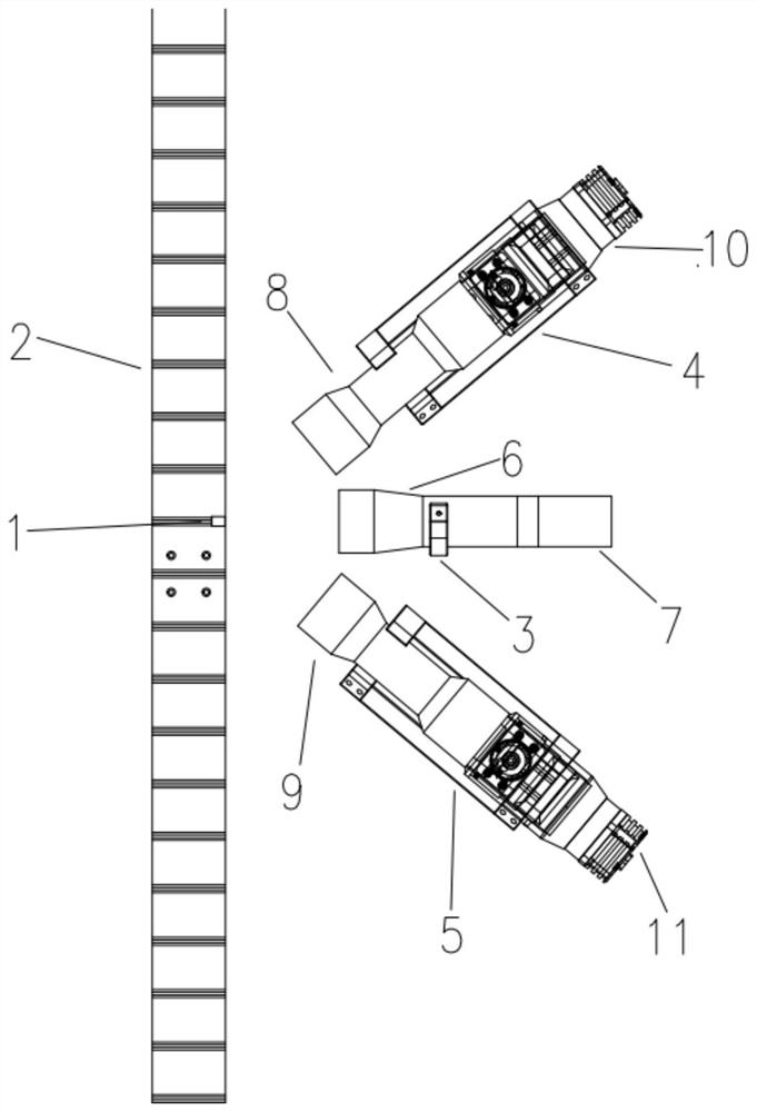
[0036] The composition structure of the detection device of the exemplary MOX fuel pellet end surface defect area of ​​the present invention is as follows figure 1 As shown, it includes a support frame 2, a camera 7, a first light source 10, a second light source 11, an image acquisition device, an image processing device, and a control system (the image acquisition device, the image processing device, and the control system are all in figure 1 not shown). The detection device is a modular detection device, and can be placed in a glove box for operation, maintenance and replacement.

[0037] The support frame 2 on which the fuel pellets 1 are placed drives the fuel pellets 1 for loading and unloading under the control of the control system.

[0038] The camera 7 is used to take an image of the end face of the fuel pellet 1 facin...


PUM


Abstract

The invention belongs to the technical field of nuclear fuel element detection, and relates to a detection device and a detection method for the defect area of ​​the end surface of MOX fuel pellets. The detection device includes a camera, a first light source, a second light source, an image acquisition device, an image processing device, and a control system. The camera is used to take an image of the end face of the fuel pellet facing it; the first light source and the second light source are respectively located at The two sides of the camera are used to turn on separately or simultaneously to provide light sources for camera shooting; the image acquisition device completes image acquisition according to the images captured by the camera; the image processing device processes the images collected by the image acquisition device, and calculates the MOX fuel pellets The defect area of ​​the end surface; the control system is used to control the loading and unloading of fuel pellets, the switching of the first light source and the second light source, and the shooting of the camera. The detection device and method of the present invention can be used for automatic, high-efficiency, and high-precision calculation and judgment of the defect area of ​​the end surface of the MOX fuel pellet, without being affected by its reflective performance.

Description

technical field [0001] The invention belongs to the technical field of nuclear fuel element detection, and relates to a detection device and a detection method for the defect area of ​​the end surface of MOX fuel pellets. Background technique [0002] MOX fuel pellets are based on UO 2 Powder and PuO 2 Powder is the raw material, and the ceramic body is made by mechanical mixing, pressing and sintering. It is widely used as nuclear fuel in pressurized water reactors and fast reactors. The appearance defects of fuel pellets will cause uneven heating of fuel rod cladding, resulting in cladding damage and nuclear accidents. Because of this, it is necessary to prove that the integrity of the appearance of each MOX fuel pellet meets the design requirements before loading tubes, and conduct 100% visual defect inspection on all pellets to ensure smooth tube loading and safe operation of the reactor. Among them, end face defect is the most common appearance defect in fuel pellets...

Claims


Application Information

Patent Timeline
Patent Type & Authority Patents(China)
IPC IPC(8): G01B11/28G01N21/01G01N21/95
CPCG01B11/285G01N21/01G01N21/95
Inventor 李铁成刘明袁平罗浩
Owner CHINA NUCLEAR POWER ENG CO LTD
Learn More