
Air pressurization type sealing quick insertion gun head

A technology of air pressurization and gun insertion, which is applied to equipment loaded into pressure vessels, gas/liquid distribution and storage, ship construction details, etc. It can solve problems such as increasing the work intensity of liquid filling personnel, increased wear of parts, and inability to use them , to achieve the effect of increasing the protection effect, increasing the sealing performance and reasonable structure

Inactive Publication Date: 2018-09-18
歌思(天津)低温设备有限公司
View PDF5 Cites 0 Cited by
  • Summary
  • Abstract
  • Description
  • Claims
  • Application Information

AI Technical Summary

Problems solved by technology

[0002] With the application and popularization of LNG facilities, there are more and more urban LNG buses, taxis, short-distance passenger vehicles, and transport vehicles. Different liquid filling vehicles have different heights from the filling port to the ground. The weight of the filling gun is generally heavy. When the distance between the filling port of the filling truck and the ground is high, the heavy filling gun will often increase the work intensity of the filling personnel. At the same time, the filling gun is heavy. Among them, there are many mechanical parts for adding liquid, which will easily lead to aggravated wear of each part, leakage, or even unusable

Method used


Image

  • Air pressurization type sealing quick insertion gun head
  • Air pressurization type sealing quick insertion gun head
  • Air pressurization type sealing quick insertion gun head

Examples


Embodiment Construction

[0018] In order to make the technical means, creative features, goals and effects achieved by the present invention easy to understand, the present invention will be further described below in conjunction with specific embodiments.

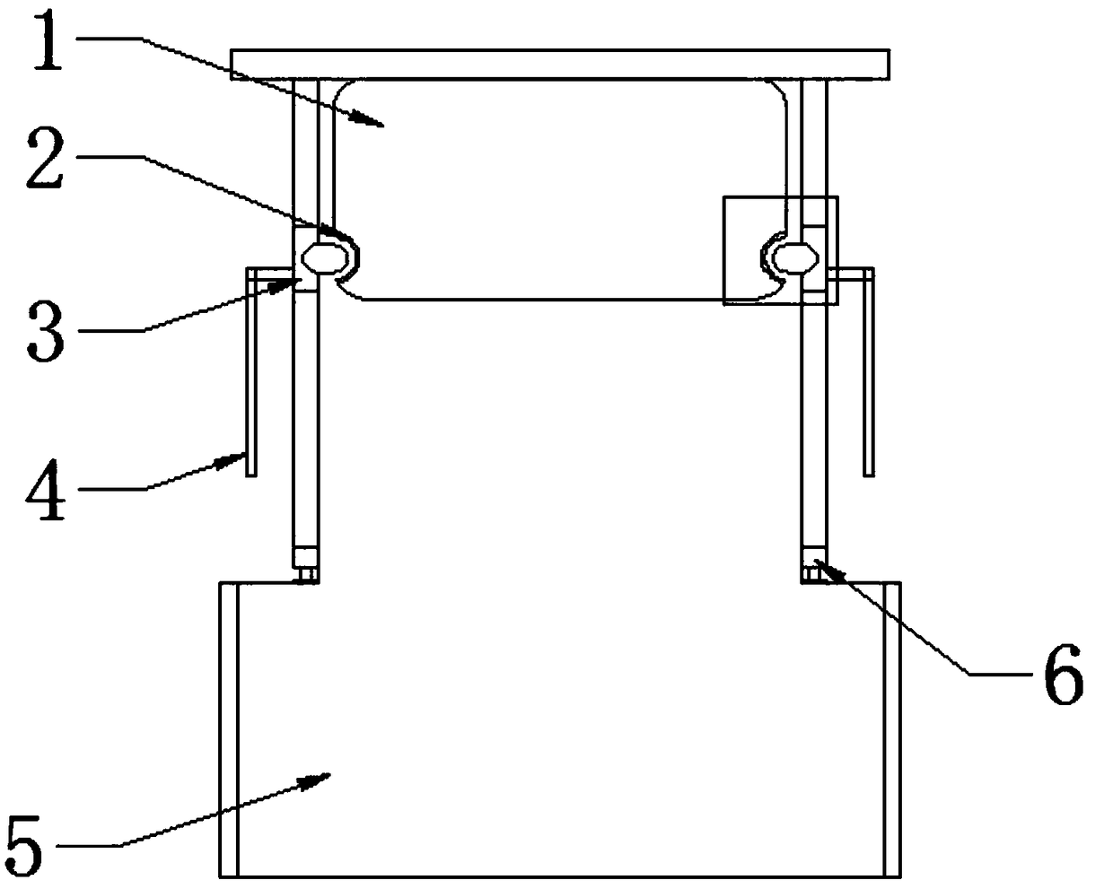
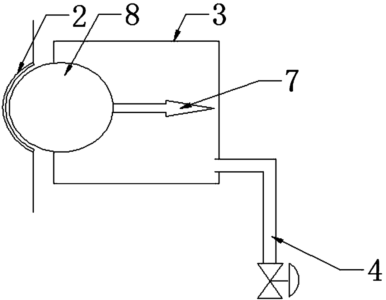
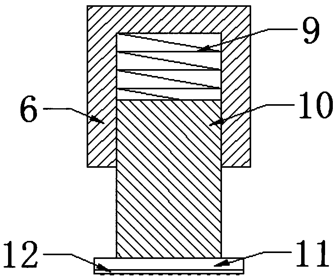
[0019] see Figure 1-Figure 3 , the present invention provides a technical solution: an air pressurized sealed quick-insert gun head, including a gun-inserting seat 1, a driving air source 4, and a liquid-filling muzzle 5, and a liquid-filling muzzle is installed on the front end of the gun-inserting base 1 5. The left and right sides of the gun insertion seat 1 are symmetrically provided with the gun insertion groove 2, the left side of the gun insertion groove 2 is provided with a gasket inner cavity 3, and the left end of the gasket inner cavity 3 is equipped with a driving air source 4, sealed There is a tension spring 7 on the right side of the pad inner cavity 3, and a PTFE sealing ball 8 is provided on the left end of the tension spring 7. ...


PUM


Abstract

The invention provides an air pressurization type sealing quick insertion gun head. The air pressurization type sealing quick insertion gun head comprises insertion gun nozzle grooves, sealing gasketinner chambers, fixed rods, tension springs, polytetrafluoroethylene sealing balls, buffer springs, connecting rods, buffer plates and protective pads, the insertion gun nozzle grooves are symmetrically arranged in the left side and the right side of an insertion gun seat, the sealing gasket inner chambers are arranged at the left sides of the insertion gun nozzle grooves, the tension springs arearranged at the internal right sides of the sealing gasket inner chambers, the polytetrafluoroethylene sealing balls are arranged on the left end surfaces of the tension springs, and the above designsolves the problem of incomplete sealing storage of an original liquid charging gun. The fixed rods are arranged at the left side and the right side of the rear end surface of the liquid charging gun,the buffer springs are mounted at the internal rear sides of the fixed rods, the connecting rods are mounted on the front end surfaces of the buffer springs, the buffer plates are mounted on the front end surfaces of the connecting rods, and the protective pads are arranged on the front end surfaces of the buffer plates, and the above design solves the problem of very easy wearing of the originalliquid charging gun. The air pressurization type sealing quick insertion gun head has the advantages of reasonable structure, safety in use, wearing avoiding and good sealing effect.

Description

technical field [0001] The invention relates to an air-pressurized sealed quick-insertion gun head, which belongs to the field of mechanical automation. Background technique [0002] With the application and popularization of LNG facilities, there are more and more urban LNG buses, taxis, short-distance passenger vehicles, and transport vehicles. Different liquid filling vehicles have different heights from the filling port to the ground. The weight of the filling gun is generally heavy. When the distance between the filling port of the filling truck and the ground is high, the heavy filling gun will often increase the work intensity of the filling personnel. At the same time, the filling gun is heavy. Among them, there are many mechanical parts for adding liquid, which will easily lead to aggravated wear of each part, leakage, or even unusability. It can be seen that the prior art needs to be further improved, and there is an urgent need for an air-pressurized sealed quick...

Claims


Application Information

Patent Timeline
Patent Type & Authority Applications(China)
IPC IPC(8): F17C5/02F17C13/00
CPCF17C5/02F17C13/00F17C2205/0302
Inventor 万云生
Owner 歌思(天津)低温设备有限公司
Learn More