


Quick Research
Generate reliable direction feasibility study reports for your R&D in just a few steps.

Technical Q&A
Discover and master advanced knowledge NOW. Basics, ideas, possibilities, all at once.

Find Solutions
As an expert in R&D theories, this can generate solutions to your technical problems instantly.

Evaluate Feasibility
Analyze your overall solution with one click, know your potential R&D risks in advance.

Monitor Landscape
Get weekly tech updates, stay abreast of the latest tech innovations and key insights.
Decompression device and decompression method used for tube drawing
A decompression device and pipe fitting technology, which is applied in the field of pipe drawing and plastic forming, can solve the problems of pipe fitting wrinkling, weld cracking, uneven thickness, etc., and achieve the effects of avoiding wrinkles, prolonging service life, and low manufacturing cost
- Summary
- Abstract
- Description
- Claims
- Application Information
AI Technical Summary
Problems solved by technology
Method used
Image

Examples
Embodiment 1
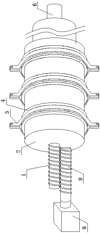
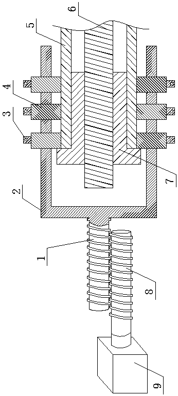
[0036] as attached figure 1 And attached figure 2 As shown, a decompression device for pipe fittings drawing includes a locking device and a reverse force application device. The locking device includes a drive screw 1 and a locking assembly, and the locking assembly is assembled on a pipe fitting 5 with a built-in inner core. and firmly cooperate with the pipe fitting 5, and the locking assembly is fixedly matched with the pipe fitting 5 and the inner core, the transmission screw 1 is connected with the locking assembly, and the central axis of the transmission screw 1 is set coaxially with the central axis of the pipe fitting 5; reverse force The device includes a reverse drive device and a decompression screw, the axis of the decompression screw is arranged side by side with the axis of the transmission screw 1 up and down, the decompression screw and the transmission screw 1 are connected by thread engagement, and the reverse drive device is connected with the decompressi...
Embodiment 2
[0049] A decompression method for drawing pipe fittings. A decompression device for drawing pipe fittings disclosed in Embodiment 1 is assembled on the end of a pipe fitting 5 with a built-in inner core. The decompression device slows down the traveling speed of the pipe fitting 5 so as to provide the pipe fitting 5 with a reverse pulling force with a decompression effect.
[0050] Specifically, the decompression device is assembled on the tail end of the pipe fitting 5, and the decompression screw is rotated at a speed lower than the advancing speed of the pipe fitting 5 by adjusting the reverse drive device, and the decompression screw hinders the pipe fitting 5 through the transmission screw 1. The progress of the pipe is equivalent to applying a pulling force to the pipe 5 opposite to the direction of travel of the pipe 5 .
PUM
 Abstract
Description
Claims
Application Information
 - R&D Engineer
- R&D Manager
- IP Professional
- Industry Leading Data Capabilities
- Powerful AI technology
- Patent DNA Extraction
Browse by: Latest US Patents, China's latest patents, Technical Efficacy Thesaurus, Application Domain, Technology Topic, Popular Technical Reports.
© 2024 PatSnap. All rights reserved.Legal|Privacy policy|Modern Slavery Act Transparency Statement|Sitemap|About US| Contact US: help@patsnap.com