
Rapid escape equipment for high floor

A high-floor and fast technology, applied in life-saving equipment, building rescue, etc., can solve the problems of low escape efficiency, limited lift height, and difficult personnel evacuation, to ensure escape safety, enhance clamping effect, and simple structure. Effect

Pending Publication Date: 2018-09-18
SHANDONG UNIV OF SCI & TECH
View PDF5 Cites 1 Cited by
  • Summary
  • Abstract
  • Description
  • Claims
  • Application Information

AI Technical Summary

Problems solved by technology

[0002] When a fire breaks out in a high-rise building, the fire spreads quickly and evacuation is difficult. It is often accompanied by power outages, elevators stop running, and stairs are blocked by thick smoke. Most of the escapees in the building can only wait for rescue. The current rescue method is mainly firefighting. The team used elevators and air cushions for rescue. Due to the limited ascending height of the elevators, people on slightly higher floors still could not climb up the elevators to be rescued; at the same time, the area for laying air cushions was limited, and falling from a high place could not guarantee that they would land on the ground first. Secondly, even if it falls on the air cushion, it is easy to fall, and by the time the rescuers and equipment arrive at the disaster scene, the best escape time has passed
Therefore, the escape method that above two kinds of commonly used rescue high-rise fires take place all can not fundamentally solve the problem of high-rise escape
[0003] Because the existing high-rise escape appliances, such as mechanical ladders, aerial baskets, air cushions, etc., all belong to the category of fire rescue tools, their installation and use require professional skills, and there is no wide operability; they wait for rescue and equipment installation. It takes a lot of time to delay the escape time; most rescue equipment requires multiple people to cooperate to escape, and the escape efficiency is low

Method used


Image

  • Rapid escape equipment for high floor
  • Rapid escape equipment for high floor
  • Rapid escape equipment for high floor

Examples


Embodiment Construction

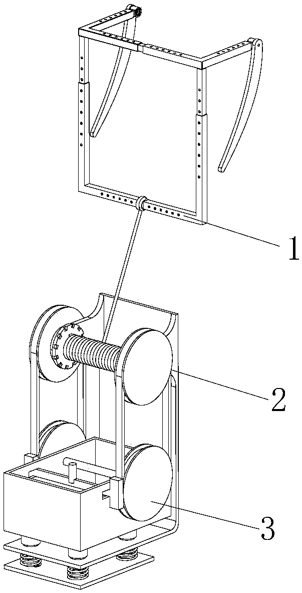
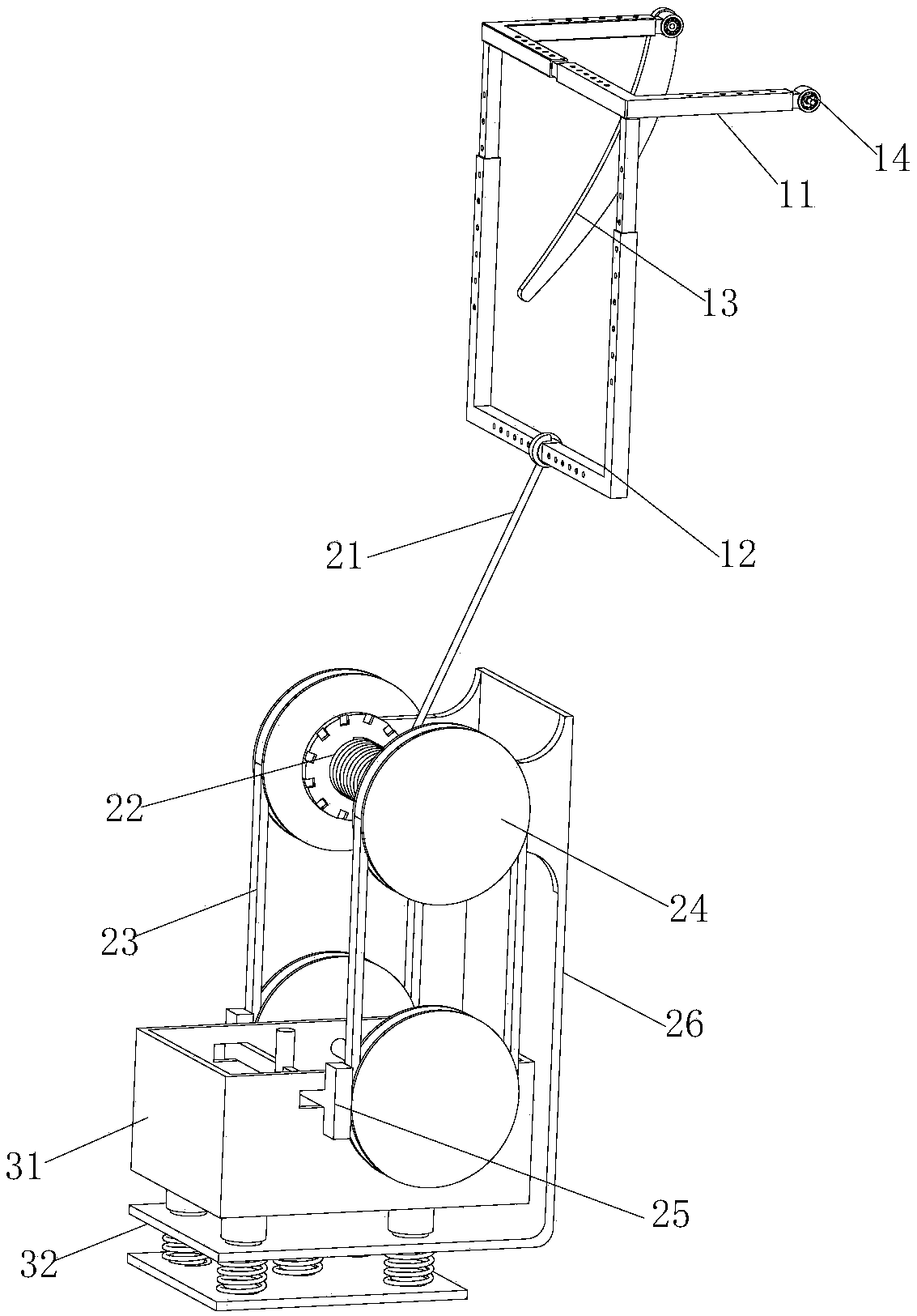
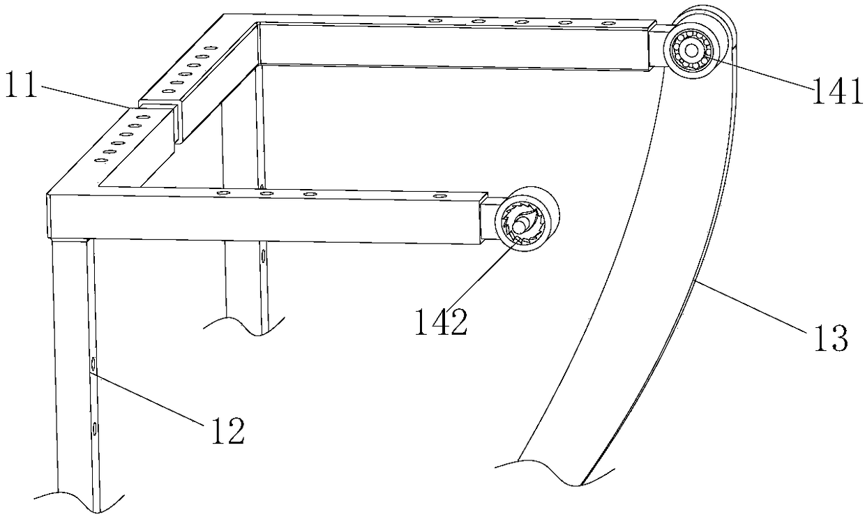
[0019] combine Figure 1 to Figure 4 As shown, the specific implementation of a high-floor rapid escape device provided by the present invention is as follows.

[0020] Such as figure 1 As shown, a high-floor rapid escape device specifically includes a fixing device 1, a rope winding device 2 and a riding device 3. The fixing device 1 is installed on the inside and outside of the balcony, and the rope winding device 2 is connected to the fixing device 1 and the riding device 3. The device 2 has the function of decelerating the rope winding; the riding device 3 is arranged below the rope winding device, and the bottom of the riding device 3 is provided with a buffer base 32 . The device has the advantages of simple structure, convenient installation, etc., realizes the function of rapid escape from high floors, and realizes the function of controllable falling speed, thereby ensuring the safety of escape.

[0021] Such as figure 2 and image 3 As shown, the fixing device 1...


PUM


Abstract

The invention provides rapid escape equipment for a high floor. The technical effect of rapid safe escape from the high floor under the conditions of outbreak of fire and the like is achieved. The equipment comprises a fixing device, a rope winding device and a riding device. The fixing device is installed on the inner and outer sides of a balcony and particularly comprises symmetrically-arrangedclamping adjusting devices and two supporting fixing frames matched with the clamping adjusting devices, the supporting fixing frames are of telescopic structures and provided with multiple telescopicrod adjusting holes so as to adapt to different balcony sizes and adjust the fixing width, the rope winding device comprises a bearing rope, a rope sheave, friction belts, friction wheels, friction pieces and a rope sheave support, the supporting fixing frames and the rope sheave are connected through the bearing rope, and the rope winding device has the decelerated rope winding function. The riding device is arranged below the rope winding device, the bottom of the riding device is provided with a buffer base, and particularly the bottom of the riding device is provided with multiple springforming clamping plate structures. The rapid escape equipment further has the advantages of being convenient to install, high in applicability, easy and convenient to operate, safe, reliable and the like.

Description

technical field [0001] The invention relates to the field of escape equipment, in particular to a high-floor rapid escape equipment. Background technique [0002] When a fire breaks out in a high-rise building, the fire spreads quickly and evacuation is difficult. It is often accompanied by power outages, elevators stop running, and stairs are blocked by thick smoke. Most of the escapees in the building can only wait for rescue. The current rescue method is mainly firefighting. The team used elevators and air cushions for rescue. Due to the limited ascending height of the elevators, people on slightly higher floors still could not climb up the elevators to be rescued; at the same time, the area for laying air cushions was limited, and falling from a high place could not guarantee that they would land on the ground first. Secondly, even if it falls on the air cushion, it is easy to fall, and by the time rescuers and equipment arrive at the disaster scene, the best escape time...

Claims


Application Information

Patent Timeline
IPC IPC(8): A62B1/14A62B1/18
CPCA62B1/14A62B1/18
Inventor 陈天祥折宝斌
Owner SHANDONG UNIV OF SCI & TECH
Learn More