
pressure relief device

A technology of pressure and equipment, which is applied in the field of pressure release equipment for shells, can solve the problems of expensive manufacturing, expensive maintenance, complex structure, etc., and achieve the effect of simple structure, low manufacturing cost and low maintenance cost

Active Publication Date: 2020-12-18
ABB (SCHWEIZ) AG
View PDF11 Cites 0 Cited by
  • Summary
  • Abstract
  • Description
  • Claims
  • Application Information

AI Technical Summary

Problems solved by technology

[0005] The problem associated with such pressure relief devices is that, due to their complex structure, they are generally relatively expensive to manufacture and / or relatively expensive to maintain if, after their operation, the pressure relief device or a part thereof, for example, needs to be replaced. expensive

Method used


Image

  • pressure relief device
  • pressure relief device
  • pressure relief device

Examples


Embodiment Construction

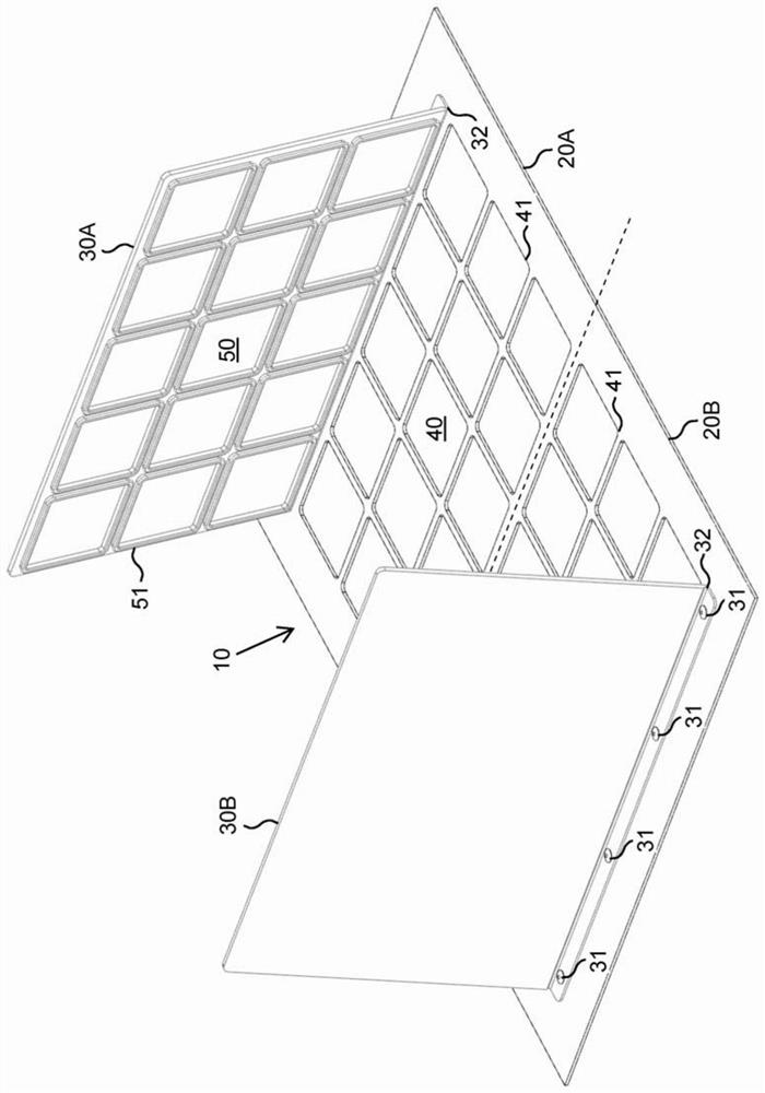
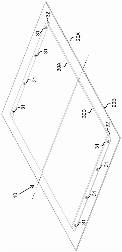
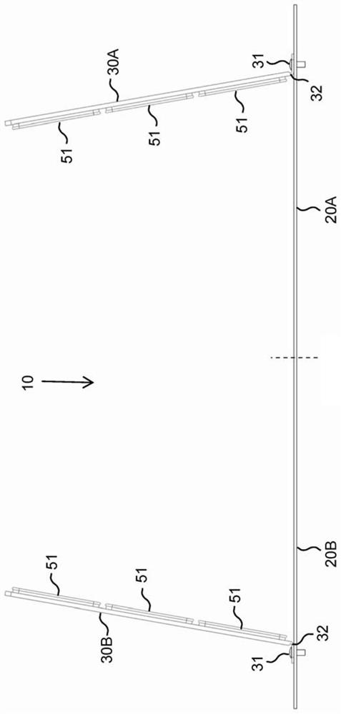
[0018] According to an embodiment, the pressure relief device has a first side and a second side. According to an embodiment, the pressure relief device comprises at least one pressure relief device comprising: a base provided with a set of openings therethrough; and a cover comprising a set of protrusions corresponding to the set of openings of the base. According to an embodiment, in the closed position of the cover, each protrusion of said set of protrusions is configured to extend inwards into a corresponding opening of the set of openings and to close the openings in a sealing manner. According to an embodiment, in the open position of the cover, the protrusions of the set of protrusions are configured to be removed from the openings of the set of openings. According to an embodiment, the cover is configured to move from its closed position into its open position in response to the pressure in the second side of the pressure relief device exceeding the pressure in the fir...


PUM


Abstract

A pressure relief device (10) comprising at least one pressure relief device, the pressure relief device comprising a base (20A, 20B) and a cover (30A, 30B), the base is provided with a set of openings (40) passing through the base, the cover comprises a protrusion A set (50), wherein each protrusion (51) of the set of protrusions is configured to extend inwardly into a corresponding opening (41) of the set of openings in a closed position of the cover and to close the opening in a sealing manner, and the protrusions (51) is configured to be removed from the opening (41) in the open position of the cover, and wherein the cover (30A, 30B) is configured to exceed the pressure release in response to pressure in the second side of the pressure relief device (10) The pressure in the first side of the device moves into the open position by at least a predetermined threshold.

Description

technical field [0001] The present invention relates to a pressure relief device, and in particular to a pressure relief device for an enclosure. Background technique [0002] For example, electrical equipment such as electrical equipment and / or electronic equipment placed outdoors may require protection from adverse conditions. This protection can be accomplished by suitable enclosures around electrical equipment. Examples of enclosures for electrical equipment are indoor or outdoor cabinets made of plastic and / or metal, which may be used to protect the contents from the environment and also to prevent eg electric shock to the user of the equipment. [0003] For example, such enclosures for electrical equipment may be provided with pressure relief devices, such as explosion vents, safety covers or rupture panels, in order to reduce excessive pressure differences between the interior and exterior of the enclosure and, for example, avoid damage to the enclosure and Causes f...

Claims


Application Information

Patent Timeline
Patent Type & Authority Patents(China)
IPC IPC(8): H05K5/06
CPCH05K5/068H02B13/025
Inventor 托尼·尼格伦马蒂·凯佩尼科·比约克曼韦利·塞斯基拉赫蒂
Owner ABB (SCHWEIZ) AG
Learn More