
Cinnabar cutting device

Inactive Publication Date: 2018-09-14
贵州拙意堂文化发展有限公司
View PDF6 Cites 0 Cited by
  • Summary
  • Abstract
  • Description
  • Claims
  • Application Information

AI Technical Summary

Problems solved by technology

[0002] The company designed a cinnabar cutting device in the early stage, but in the actual debugging process, it was found that in order to ensure the accurate cutting position, other mechanical arms are needed to assist in fixing, but the existing mechanical arms are expensive, and the structure is complicated and easy to cause interference, so the company needs a structure A leaner, lower-cost solution

Method used


Image

  • Cinnabar cutting device

Examples


Embodiment Construction

[0016] The technical solution of the present invention is further described below, but the scope of protection is not limited to the description.

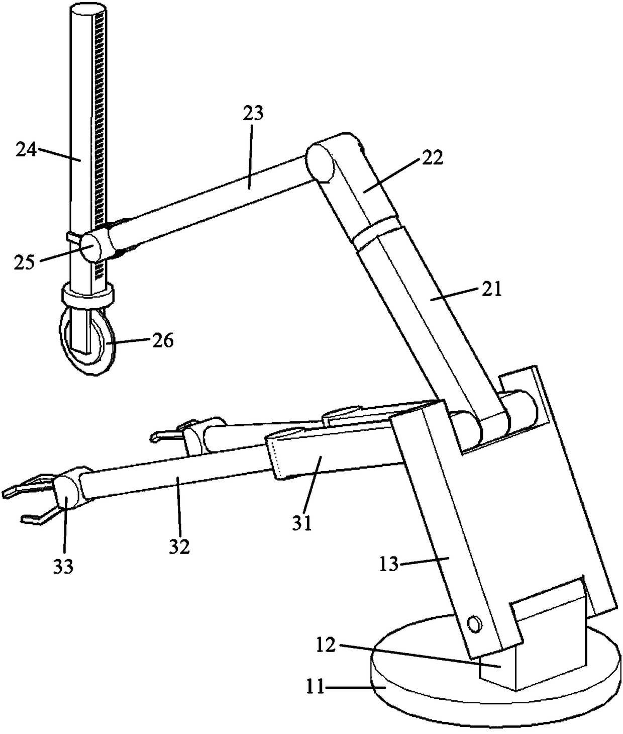
[0017] Such as figure 1 A kind of cinnabar cutting device shown comprises a base 11, a base 12, and a total action block 13; The upper end of the action block 13 is rotatably fixed with a middle first action bar 21 and a side first action bar 31, wherein the side first action bar 31 is two sides respectively located at the middle first action bar 21, and the middle first action bar 21 front end The second action bar 22 is rotatably fixed, the third action block 23 is fixed at the front end of the second action bar 22, the operation block 25 is fixed at the front end of the third action block 23, and the telescopic sleeve rod 24 is installed on the operation block 25 , telescopic cover rod 24 telescopic lower ends are fixedly equipped with cutter 26, the front end of the first action bar 31 of the limit is rotatably fixed with the ...


PUM


Abstract

The invention provides a cinnabar cutting device which comprises a base, a foundation bed and a main action block. The foundation bed is perpendicularly fixed onto the horizontal base; the main actionblock is rotatably fixed to the upper end of the foundation bed; a middle first action bar and side first action rods are rotatably fixed to the upper end of the main action block; the two side firstaction rods are located on two sides of the middle first action bar; a middle second action bar is rotatably fixed to the front end of the middle first action bar; a middle third action bar is fixedto the front end of the middle second action bar; an operation block is fixed to the front end of the middle third action bar; a telescopic sleeve rod is installed on the operation block; a cutter isfixedly arranged at the telescopic lower end of the telescopic sleeve rod; side second action rods are rotatably fixed to the front ends of the side first action rods; and grab clamping jaws are fixedto the front ends of the side second action rods. According to the cinnabar cutting device provided by the invention, through a structure with branch control by the two clamping jaws and one cutter as well as summarized displacement control by the main action block, the equipment cost for cinnabar cutting can be effectively and greatly reduced, and the occurrence of machine interference is effectively reduced.

Description

technical field [0001] The invention relates to a cinnabar cutting device. Background technique [0002] The company designed a cinnabar cutting device in the early stage, but in the actual debugging process, it was found that in order to ensure the accurate cutting position, other mechanical arms are needed to assist in fixing, but the existing mechanical arms are expensive, and the structure is complicated and easy to cause interference, so the company needs a structure A leaner, lower-cost solution. Contents of the invention [0003] In order to solve the above technical problems, the present invention provides a cinnabar cutting device. The cinnabar cutting device is controlled by two jaws and a cutter branch, and the displacement is controlled by the general action block, which can effectively and greatly reduce the equipment required for cinnabar cutting. cost, and effectively reduce the occurrence of mechanical interference. [0004] The present invention is achie...

Claims


Application Information

Patent Timeline
Patent Type & Authority Applications(China)
IPC IPC(8): B28D1/24B28D7/04B28D7/00
CPCB28D1/24B28D7/00B28D7/04
Inventor 田小江
Owner 贵州拙意堂文化发展有限公司
Learn More