
Sausage filling device

A filling device and sausage technology, applied in the field of food processing, can solve the problems of rolling back and forth, difficult positioning, etc., and achieve the effect of obvious application effect and saving equipment investment.

Inactive Publication Date: 2018-09-14
王炳钦
View PDF16 Cites 5 Cited by
  • Summary
  • Abstract
  • Description
  • Claims
  • Application Information

AI Technical Summary

Problems solved by technology

This structure does not involve the improvement of filling, and this kind of large-scale sausage processing equipment usually comes from foreign manufacturers, which is limited by the monopoly of core technology
[0004] In addition, conventional sausages have a cylindrical structure. During the frying process, this type of sausage has the problem of rolling. When the sausage is eaten with bread slices, it also has the problem of rolling back and forth and difficult positioning.

Method used


Image

  • Sausage filling device
  • Sausage filling device
  • Sausage filling device

Examples


Embodiment 1

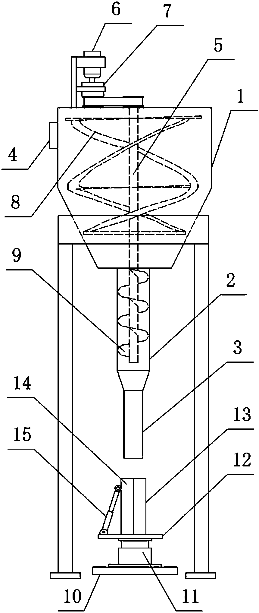
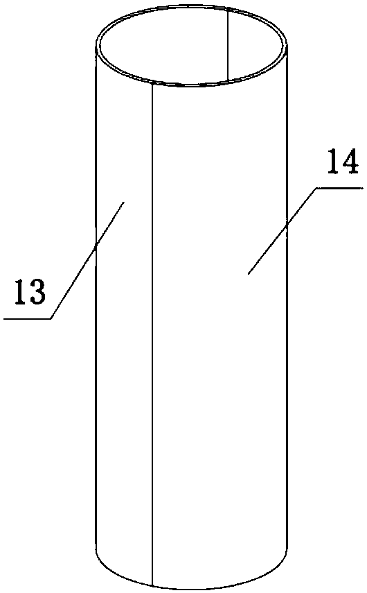
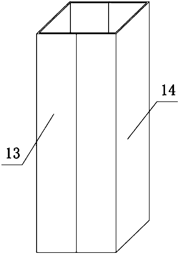
[0028] like Figure 1 to Figure 3 As shown, the present invention includes a stirring and filling mechanism and a supporting mechanism,

[0029] The stirring and filling structure includes, from top to bottom, a stirring shell 1, a filling shell 2, a frustoconical transition pipe 20 and a feeding pipe 3 that are fixedly connected and communicated in sequence. The side wall of the stirring shell 1 is provided with a feeding port 4, and the The top is provided with a rotating shaft 5 in a vertical direction, a motor 6 and a reducer 7 are arranged on the outer side of the top of the stirring shell 1, the output shaft of the motor 6 is connected with the input shaft of the reducer 7, and the upper end of the rotating shaft 5 extends into the outer side of the stirring shell 1 It is connected with the output shaft of the reducer 7 through a belt drive. The part of the rotating shaft 5 located in the stirring and filling mechanism has a plurality of screw-type stirring paddles 8 and...

Embodiment 2

[0034] The structure of this embodiment is basically the same as that of the first embodiment, the difference is: Figure 5 As shown, the first template 13 is provided with a through hole and a push-up mechanism, the push-up mechanism includes a push rod, a spring 16 and a fixed seat 17, and the push rod includes a first push rod 18 and a second push rod 19 that are integrally formed. The ejector rod 18 is slidably arranged in the through hole, the spring 16 is sleeved on the outer wall of the first ejector rod 18, the outer diameter of the first ejector rod 18, the outer diameter of the spring 16, and the outer diameter of the second ejector rod 19 increase in sequence, and the spring 16 The two ends of the spring 16 are respectively in contact with the outer wall of the first template 13 and the second ejector rod 19 , the spring 16 is located in the fixed seat 17 , and the end of the second ejector rod 19 away from the first ejector rod 18 extends out of the fixed seat 17 . ...


PUM


Abstract

The invention belongs to the technical field of food processing, and particularly relates to a sausage filling device. The device comprises a stirring filling mechanism and a supporting mechanism; thestirring filling structure comprises, from top to bottom, a stirring shell, a filling shell, a feeding pipe and a rotating shaft in turn which are fixedly connected to each other and communicate witheach other; spiral stirring paddles and a spiral feeding plate are arranged on the rotating shaft; the supporting mechanism comprises a base, a first telescopic cylinder and a receiving plate; the upper end surface of the receiving plate is fixedly connected to a first mold plate, and is hinged to a second mold plate; a sausage forming cavity is formed between the first mold plate and the secondmold plate; a second telescopic cylinder is arranged between the upper end of the second mold plate and the receiving plate; and two ends of the second telescopic cylinder are separately hinged to thereceiving plate and the second mold plate. With the provided stirring filling mechanism and the supporting mechanism, the device realizes the stirring of meat and the forming of sausages. Meanwhile,a self-separated mold plate structure is designed, and is convenient for staff to take out sausages.

Description

technical field [0001] The invention belongs to the technical field of food processing, and particularly relates to a sausage filling device. Background technique [0002] Sausage is a fast food, not only has a unique flavor, but also suitable for all ages. The traditional method of making sausages is usually to manually make casings, and then pour the seasoned meat into the casings, and seal the ends for preservation. Steaming, frying and stewing can be done, but this method is only suitable for small-scale household processing, and cannot meet the needs of sausage processing plants. [0003] In order to meet the needs of most people, many manufacturers have begun to use large-scale processing machinery to process and produce sausage food in batches. For example, Authorized Announcement No. CN101028017B discloses a filling device for filling paste-like materials, which has a hopper and is arranged in the hopper. The conveying mechanism below and the feeding device for feed...

Claims


Application Information

Patent Timeline
Patent Type & Authority Applications(China)
IPC IPC(8): A22C11/08A22C7/00
CPCA22C7/0092A22C11/08
Inventor 王炳钦
Owner 王炳钦
Learn More