Pressure relieving pipeline

A technology for pressure relief pipes and pipes, applied to pipe components, pipes/pipe joints/fittings, mechanical equipment, etc., can solve the problems of pipe wall fatigue failure and reduce the service life of pipes, so as to improve service life, effectively unload, Simple and reasonable structure

Pending Publication Date: 2018-09-11
SUZHOU BAODI TUBE CO LTD
View PDF10 Cites 2 Cited by
  • Summary
  • Abstract
  • Description
  • Claims
  • Application Information

AI Technical Summary

Problems solved by technology

The existing pipeline itself does not have a pressure relief device. Because the pressure in the pipeline is very unstable, the repeated action of variable load on the pipe wall is prone to fatigue failure, which greatly reduces the service life of the pipeline.

Method used


Image

  • Pressure relieving pipeline
  • Pressure relieving pipeline
  • Pressure relieving pipeline

Examples


Embodiment Construction

[0015] The following will clearly and completely describe the technical solutions in the embodiments of the present invention with reference to the accompanying drawings in the embodiments of the present invention. Obviously, the described embodiments are only some, not all, embodiments of the present invention.

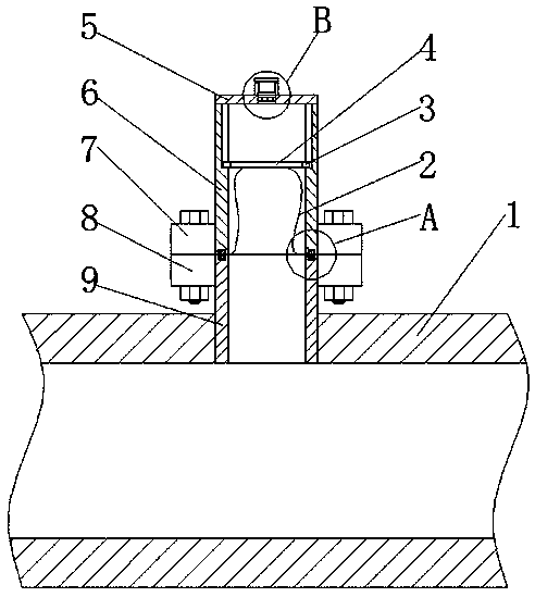
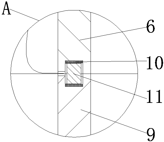
[0016] refer to Figure 1-3 , a pressure relief pipeline, comprising a pipeline 1, the side wall of the pipeline 1 is fixedly connected with a first connecting pipe 9, the first connecting pipe 9 communicates with the inner cavity of the pipeline 1, and the side wall of the first connecting pipe 9 is fixedly connected There is a first fixed block 8, the upper side of the first connecting pipe 9 is provided with a second connecting pipe 6, the side wall of the lower end of the second connecting pipe 6 is fixedly connected with a second fixed block 7, the second fixed block 7 is connected with the first A fixed block 8 offsets each other, and the second fixed block 7 a...


PUM


Abstract

The invention discloses a pressure relieving pipeline which comprises a pipeline body, wherein a first connecting pipe is fixedly connected to the side wall of the pipeline body; the first connectingpipe communicates to the inner cavity of the pipeline body; a first fixed block is fixedly connected to the side wall of the first connecting pipe; a second connecting pipe is arranged on the upper side of the first connecting pipe; a second fixed block is fixedly connected to the side wall at the lower end of the second connecting pipe; the second fixed block leans against the first fixed block;the second fixed block and the first fixed block are fixedly connected through a bolt; two sliding chutes are symmetrically formed in the inner wall of the second fixed block; slide blocks are slidably connected in the two sliding chutes; and a baffle plate is fixedly and jointly connected to the two slide blocks. The pressure relieving pipeline disclosed by the invention is simple and reasonablein structure, and can unload effectively to reduce the dynamic load acted to the inner wall of the pipe, so that the service life of the pipeline is prolonged favorably. Meanwhile, the pressure relieving pipeline is provided with an alarm device, so that the alarm device can raise the alarm when the change of pressure is relatively great.

Description

technical field [0001] The invention relates to the technical field of pipelines, in particular to a pressure relief pipeline. Background technique [0002] A pipeline is a device used to transport gas, liquid or fluid with solid particles connected by pipes, pipe connectors and valves. Usually, after the fluid is pressurized by blowers, compressors, pumps and boilers, it flows from the high-pressure part of the pipeline to the low-pressure part, and it can also be transported by the pressure or gravity of the fluid itself. Pipes are widely used, mainly in water supply, drainage, heat supply, gas supply, long-distance transportation of oil and natural gas, agricultural irrigation, hydraulic engineering and various industrial devices. The existing pipeline itself does not have a pressure relief device, because the pressure in the pipeline is very unstable, and the repeated action of variable load on the pipe wall is prone to fatigue failure, which greatly reduces the service...

Claims


Application Information

Patent Timeline
Patent Type & Authority Applications(China)
IPC IPC(8): F16L55/07
CPCF16L55/07
Inventor 张圣华任刘万
Owner SUZHOU BAODI TUBE CO LTD
Why Eureka
Try Eureka