Orthopedic-screw guiding positioning forceps

An orthopedic screw and guiding positioning technology, applied in fixers, medical science, surgical forceps, etc., can solve problems such as screw rotation and twisting

Pending Publication Date: 2018-09-07
枣庄市立医院
View PDF0 Cites 4 Cited by
  • Summary
  • Abstract
  • Description
  • Claims
  • Application Information

AI Technical Summary

Problems solved by technology

[0003] The invention provides an orthopedic screw-guided positioning pliers, which realizes screw rotation and screw-in while clamping and guiding the screw, and solves the problem that the original pliers cannot rotate and twist the screw when clamping the screw

Method used


Image

  • Orthopedic-screw guiding positioning forceps
  • Orthopedic-screw guiding positioning forceps
  • Orthopedic-screw guiding positioning forceps

Examples


Embodiment Construction

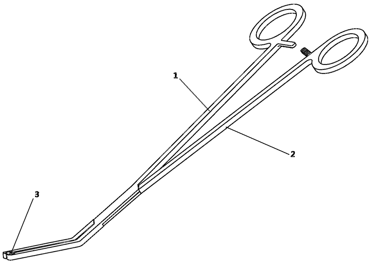
[0019] The invention is used in orthopedics to clamp the screw when installing the fixing screw, and the screw can be twisted and rotated while being clamped.

[0020] The main structure of the device is as figure 1 as shown,

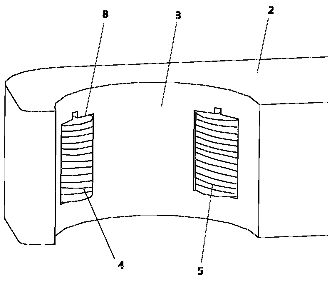
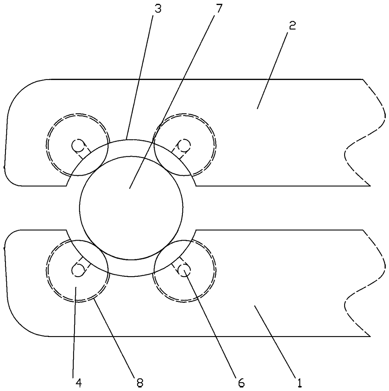
[0021] Orthopedic screw 7 guiding and positioning pliers, including a first pliers body 1 and a second pliers body 2, the front and rear ends of the first pliers body 1 and the second pliers body 2 form an angle of 120-150 degrees, the first pliers body 1 It is hingedly connected to the rear end of the second pliers body 2 at the angled position. The first pliers body 1 and the second pliers body 2 are respectively provided with arc-shaped inner grooves 3 on the inner surfaces of the clamping front ends. The groove 3 is relatively formed into a circle, and the side of the inner groove 3 of each pliers body is provided with two rotatable rollers 4, and the rotating shaft 6 of the roller 4 is arranged on the side of the inner groove 3, and the roller 4 i...


PUM


Abstract

The invention relates to orthopedic-screw guiding positioning forceps, and belongs to a tool used in the medical field. The orthopedic-screw guiding positioning forceps are characterized by comprisinga first forcep body and a second forcep body, an included angle of 120 degrees to 150 degrees is formed between the front ends of the first forcep body and the second forcep body and the back ends ofthe first forcep body and the second forcep body, the first forcep body is hinged to the second forcep body at the back end of the position of the included angle, the inner side faces of the clampingfront ends of the first forcep body and the second forcep body are each provided with an arc inner groove, and the inner grooves of the two forcep bodies are opposite to form a circle; at least two rotatable rolling shafts are arranged on the side face of the inner groove of each forcep body, rotating shafts of the rolling shafts are arranged on the side face of each forcep body, faces passed when center shafts of the rolling shafts and the front ends of the forcep bodies are open and closed and swing are perpendicular, and threads are formed in the surfaces of the rolling shafts; after the front end of the first forcep body is engaged with the front end of the second forcep body, the rolling shafts are in contact with the outer surface of an orthopedic screw, clamping force is applied tothe orthopedic screw in at least four directions, the rolling shafts are distributed at equal angle on the circle formed by the inner grooves, the orthopedic screw rotates, and the rolling shafts rotate along with the orthopedic screw.

Description

technical field [0001] The invention relates to an orthopedic screw guiding and positioning forceps, belonging to a tool used in the medical field. Background technique [0002] At present, when screwing in screws clinically in orthopedics, especially when the operating space is narrow, nail holders are often used instead of hands to hold the screws, which include left handles and right handles. The rear parts of the rods are respectively connected with tooth-shaped fixing cards, and the front ends of the two connecting rods are respectively equipped with jaws, each jaw is bent inwards to form a semicircle, and the two jaws form a circle after closing; the left handle connects the jaws of the front end of the rod Combined with the jaws at the front end of the connecting rod on the right handle, it just forms a circle, which can fix the nails in the jaws. Use the nail holder to hold the nails firmly without slipping. Difficult to operate problem. At the same time, avoid t...

Claims


Application Information

Patent Timeline
Patent Type & Authority Applications(China)
IPC IPC(8): A61B17/28A61B17/90A61B17/92
CPCA61B17/28A61B17/282A61B17/92A61B17/90
Inventor 张慎启王成斌常小猛
Owner 枣庄市立医院
Why Eureka
Try Eureka