A Closed Chain Slider Crank Combination Flower Transplanting Mechanism

A slider and crank technology, applied in the field of agricultural machinery, can solve the problems of unrealistic economic affordability of equipment introduction, difficult realization of double crank conditions, too many rod length constraints, etc., to achieve compact structure, wide optimization range, mechanism flexible effects

Active Publication Date: 2020-05-19
JINHUA VOCATIONAL TECH COLLEGE
View PDF10 Cites 0 Cited by
  • Summary
  • Abstract
  • Description
  • Claims
  • Application Information

AI Technical Summary

Problems solved by technology

[0004] 1) For electro-hydraulic and gas-integrated equipment, the structure is relatively complex and the degree of automation is quite high, so the cost is relatively expensive. However, in view of my country's existing national conditions, there are many restrictive factors for the introduction of general planting equipment, such as equipment maintenance , the economic affordability of growers and the lack of support for transplanting auxiliary operation equipment make the introduction of foreign equipment unrealistic
[0005] 2) The existing single-degree-of-freedom intermittent gear mechanism and non-circular gear planetary system transplanting mechanism are limited in the trajectory flexibility that can be achieved due to the influence of gear transmission ratio and gear characteristics. A set of gears can only achieve one trajectory. It can perform transplanting operations for pot seedling crops with the same or similar characteristics
[0006] 3) The trajectory design of the multi-rod mechanism is relatively flexible. If the parameters of the rod mechanism are optimized to achieve seedling picking and planting, the structure of the mechanism will be greatly simplified. However, the existing multi-degree-of-freedom multi-rod mechanism has too many rod length constraints, and the singularity is not easy. avoid, it will lead to difficulty in solving, it is difficult to achieve the double crank condition, and it will make the control more difficult

Method used


Image

  • A Closed Chain Slider Crank Combination Flower Transplanting Mechanism
  • A Closed Chain Slider Crank Combination Flower Transplanting Mechanism
  • A Closed Chain Slider Crank Combination Flower Transplanting Mechanism

Examples


Embodiment Construction

[0026] The present invention will be described in detail below with reference to the specific embodiments of the drawings.

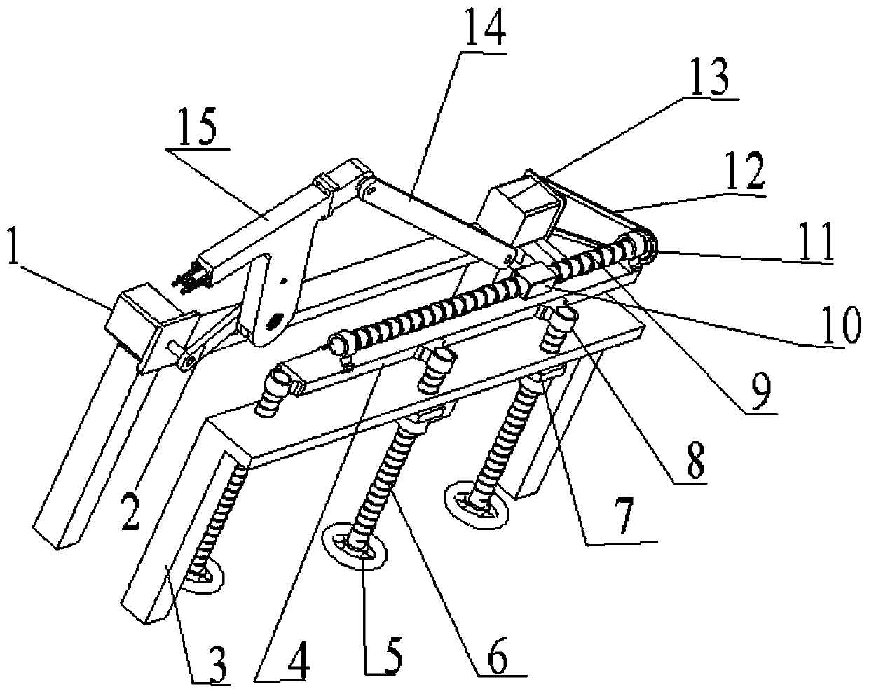
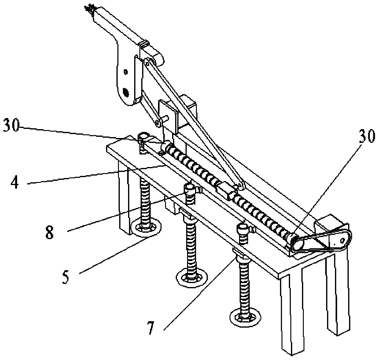
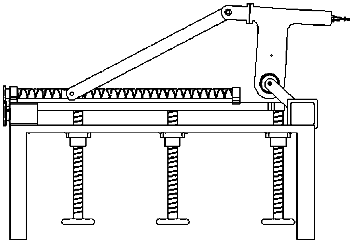
[0027] Such as figure 1 , figure 2 , image 3 , Figure 6-1 with Figure 6-2 As shown, a closed-chain slider crank combined flower transplanting mechanism includes a constant-speed motor 1, a crank 2, a movable support plate 4, a lead screw 6, a double screw shaft 9, a slider 10, a servo motor 13, and a connecting rod 14. And the seedling arm 15; the three through holes of the frame 3 are fixed with screw shaft sleeves 7; the three screw shaft sleeves 7 and the three screw rods 6 respectively constitute a spiral pair; the top of each screw 6 passes through A through hole corresponding to the frame 3, a runner 5 is fixed at the bottom end; three first bearing seats 8 are fixed on the movable support plate 4, and the top end of each screw 6 is supported on a corresponding first bearing seat through a bearing; Both ends of the double screw shaft 9 are support...


PUM


Abstract

The invention discloses a closed-chain flower-transplanting mechanism adopting a combination of a slide block and a crank. A current seedling picking mechanism has high costs and complicated structural design, or can only realize one kind of trajectory. In the invention, a double-screw shaft and a movable supporting plate form a rotating pair; the slide block and the double-screw shaft form a screw pair; a servo motor drives the double-screw shaft; a normal-speed motor drives the crank, and a cam and the crank are fixed; one end of a connecting rod is hinged with the slide block, and the otherend is hinged with a seedling taking arm end cap; the bottom of a shell is hinged with one end, where the cam is fixed, of the crank; and the movable supporting plate can adjust a height. The mechanism disclosed by the invention can realize a ''8-shaped'' trajectory or an olecranon-type trajectory to meet needs of taking seedlings and planting the seedlings, and the mechanism is simple and flexible.

Description

Technical field [0001] The invention belongs to the field of agricultural machinery and relates to flower transplanting, in particular to a closed chain slider crank combination flower transplanting mechanism. Background technique [0002] Flower transplanting technology can reduce the growth cycle of crops, maintain the uniform quality of crops, and achieve the purpose of increasing production and income. The development of automated potted flower transplanting technology is to comply with the trend of high growth rate of potted flower production, while reducing labor intensity and improving agricultural machinery With the development of flower production and facility agriculture technology in China, the foundation and conditions for vigorously developing automated potted flower transplanting technology are now available. [0003] Existing seedling removal mechanisms are mostly divided into electro-hydraulic-gas integrated manipulators, gear mechanisms, multi-degree-of-freedom lev...

Claims


Application Information

Patent Timeline
Patent Type & Authority Patents(China)
IPC IPC(8): A01G9/08
CPCA01G9/086
Inventor 周梅芳方韶华赵雄陈建能徐亚丹
Owner JINHUA VOCATIONAL TECH COLLEGE
Why Eureka
Try Eureka