Polarization beam splitting element and device

A technology of polarization beam splitting and components, applied in polarizing components, optical components, optics, etc., can solve the problems of complex structure, difficult manufacturing process, and high manufacturing cost

Inactive Publication Date: 2018-09-04
SUZHOU UNIV
View PDF6 Cites 7 Cited by
  • Summary
  • Abstract
  • Description
  • Claims
  • Application Information

AI Technical Summary

Problems solved by technology

However, its structure is more complex, the preparation process is more difficult, and the preparation cost is higher.

Method used


Image

  • Polarization beam splitting element and device
  • Polarization beam splitting element and device
  • Polarization beam splitting element and device

Examples


Embodiment 1

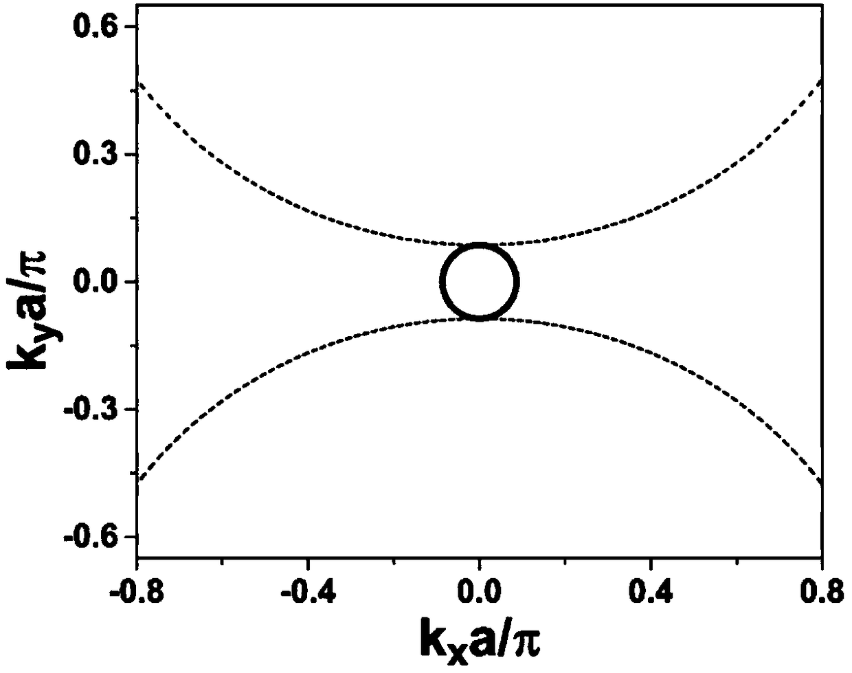
[0057] The parameters of the dielectric film and the metal film are respectively ε d =6,ε m =-2, f d = 0.25 and f m =0.75, the thickness of the periodic repeating unit is a=λ6. At this time, the equal-frequency curves of the polarization beam splitting element 4 are respectively as follows in the TE and TM modes image 3 As shown by the thick solid line and thin dashed line in (normalized frequency fa / c=0.167), it is a very small circle in TE mode, and two disjoint parabolas in TM mode. In this case, when the mixed light of TE mode and TM mode is incident on the side of the multilayer film structure along the direction parallel to the interface of the multilayer film structure (ie, the x direction), due to k y = 0, according to image 3 It can be seen from the equal frequency curve in , that there is a k greater than zero in the TE mode at this time x The solution of , means that the TE wave can propagate in the polarization beam splitting element 4; and for the TM mode,...

Embodiment 2

[0060] The parameters of the dielectric film and the metal film are respectively ε d = 1, ε m =-4, f d = 0.8 and f m =0.2, the thickness of the periodic repeating unit is a=λ / 8. At this time, the equal-frequency curves of the polarization beam splitting element 4 are respectively as follows in the TE and TM modes Figure 7 As shown by the thick solid line and the thin dashed line in (normalized frequency fa / c=0.125), the TE mode is a very small circle, and the TM mode is two intersecting parabolas. In this case, when the mixed light of TE mode and TM mode is incident on the side of the multilayer film structure along the direction parallel to the interface of the multilayer film structure (ie, the x direction), there is k y = 0, according to Figure 7 It can be seen from the equal frequency curve in , that there is a k greater than zero in the TE mode at this time x The solution of , means that the TE wave can propagate in the polarization beam splitting element 4; for t...


PUM

PropertyMeasurementUnit
Thicknessaaaaaaaaaa
Thicknessaaaaaaaaaa
Thicknessaaaaaaaaaa

Abstract

The invention relates to the field of electromagnetic wave polarization beam splitting, and discloses a polarization beam splitting element and device. The polarization beam splitting element comprises dielectric films and metal films, wherein the dielectric films and the metal films are periodically alternately stacked. A dielectric film and a metal film constitute a periodic repeating unit, andthe average dielectric constant of the periodic repeating unit is zero. When light is incident at an interface parallel to the polarization beam splitting element, transverse electric waves and transverse magnetic waves in the light can be separated due to the dispersion relationship in the polarization beam splitting element. According to the difference in the thickness ratio of the dielectric films and the metal films in the periodic repeating units, the polarization beam splitting element has two working modes which can be flexibly selected under different requirements. The polarization beam splitting element in the structure has the advantages of simple structure, easy preparation and wide material selection, is much smaller than the existing polarizing beam splitter, is easy to integrate, and has a wide application prospect in optical communications and integrated optical paths.

Description

technical field [0001] The invention belongs to the field of electromagnetic wave polarization beam splitting, and in particular relates to a polarization beam splitting element and device. Background technique [0002] Polarized light is used extensively in modern optical testing and optical applications. When an ordinary light wave propagates in an ordinary medium, it is not in a complete polarization state, but a composite state including two mutually orthogonal polarization states of a transverse electric wave (Transverse electric, TE) and a transverse magnetic wave (Transverse magnetic, TM). Polarizing beam splitters can separate these two orthogonal polarization states in space, and have extensive and important applications in traditional optical optical circuits, optical communications, and integrated optical circuits. [0003] There are three types of traditional polarizing beam splitters, mainly including: [0004] Polarizing beam splitter with dielectric multilay...

Claims


Application Information

Patent Timeline
IPC IPC(8): G02B27/28G02B5/30
CPCG02B5/30G02B27/283
Inventor 罗杰赖耘
Owner SUZHOU UNIV
Why Eureka
Try Eureka