Automatic feeding device for annular blanks

An automatic material feeding and billet technology, which is applied in the direction of conveyor objects, transportation and packaging, etc., can solve the problems of high production and maintenance costs, complex feeding devices, and easy slipping of material rings, and achieve low professional skills requirements and concise and ingenious mechanisms , debugging simple effect

Pending Publication Date: 2018-09-04
安徽省世昌智能装备科技有限公司
View PDF0 Cites 3 Cited by
  • Summary
  • Abstract
  • Description
  • Claims
  • Application Information

AI Technical Summary

Problems solved by technology

[0002] When processing annular blanks such as valve seat rings, bearing inner and outer rings, and ring gears, the traditional feeding method is to stop the equipment, manually insert the blanks into the chuck of the equipment, and then clamp them for processing. The production efficiency of the feeding method is low, there are potential safety hazards, and one person is one machine, the production capacity is low, and the labor cost is high; there are also some mechanical clamping toes and multiple sets of linear motion devices to insert the material ring into the chuck of the equipment, and then process. Although this method improves the processing efficiency, the feeding device is complicated, and the toe needs to arrange the billet neatly before picking it up, and the material ring is easy to slip during the material transfer process. When changing the product specification, it is troublesome to adjust and cumbersome to debug. High production and maintenance costs, low efficiency

Method used


Image

  • Automatic feeding device for annular blanks
  • Automatic feeding device for annular blanks
  • Automatic feeding device for annular blanks

Examples


Embodiment Construction

[0027] The embodiments of the present invention are described in detail below. This embodiment is implemented on the premise of the technical solution of the present invention, and detailed implementation methods and specific operating procedures are provided, but the protection scope of the present invention is not limited to the following implementation example.

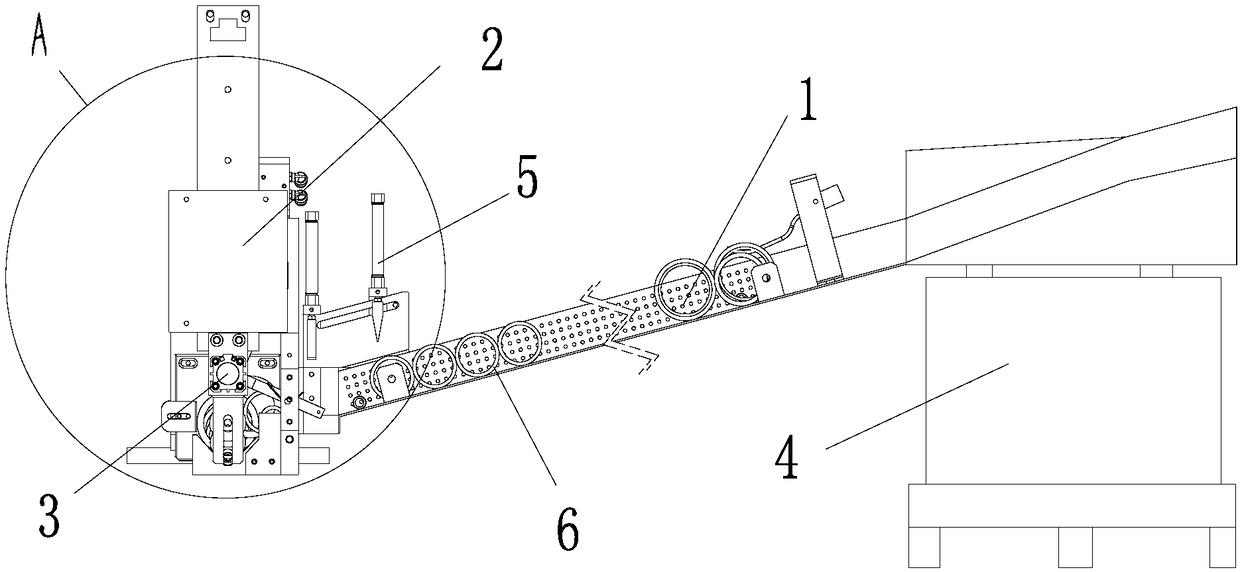
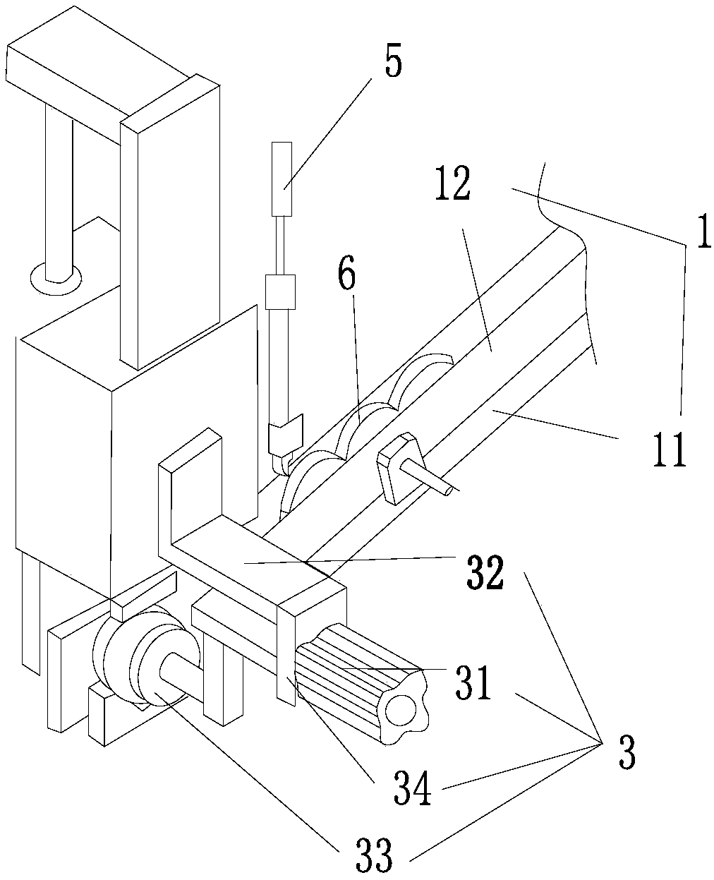
[0028] like figure 1 As shown, an automatic feeding device adapted to the annular blank 6 in this embodiment includes a feeding trough 1, a material transport mechanism 2, a material ejection mechanism 3, and a material tray 4;

[0029] This embodiment is used to transport the annular blank 6 from the tray to the position of the chuck, including a feeding trough 1 for blank delivery, a transport mechanism 2 for transporting parts from the feeding chute 1 to the chuck, The jacking mechanism 3 that pushes the parts into the chuck; the feeding chute 1 is set from high to low, starting from the blank outlet of the tra...


PUM


Abstract

The invention discloses an automatic feeding device for annular blanks. The automatic feeding device comprises a feeding trough, a conveying mechanism conveying parts from the feeding trough to the position in front of a chuck, and a pushing mechanism pushing the parts into the chuck. The feeding trough is arranged from high to low, starts at a disc and ends at the conveying mechanism. The conveying mechanism moves at a first station and a second station, at the first station, the conveying mechanism is located at the tail end of the feeding trough, and at the second station, the conveying mechanism is located in front of the chuck. The pushing mechanism is fixed to the bottom end of the conveying mechanism. The automatic feeding device has the beneficial effects that the blanks are automatically arranged on the feeding trough and automatically roll into the conveying mechanism through gravity, the conveying mechanism automatically conveys the blanks to the position in front of the chuck of machining equipment, then the parts are pushed onto the chuck by the pushing mechanism, production efficiency is improved greatly, manual clamping and conveying are not needed, and labor cost islowered.

Description

technical field [0001] The invention relates to an automatic feeding device, in particular to an automatic feeding device for an annular blank. Background technique [0002] When processing annular blanks such as valve seat rings, bearing inner and outer rings, and ring gears, the traditional feeding method is to stop the equipment, manually insert the blanks into the chuck of the equipment, and then clamp them for processing. The production efficiency of the feeding method is low, there are potential safety hazards, and one person is one machine, the production capacity is low, and the labor cost is high; there are also some mechanical clamping toes and multiple sets of linear motion devices to insert the material ring into the chuck of the equipment, and then process. Although this method improves the processing efficiency, the feeding device is complicated, and the toe needs to arrange the billet neatly before picking it up, and the material ring is easy to slip during th...

Claims


Application Information

Patent Timeline
Patent Type & Authority Applications(China)
IPC IPC(8): B65G47/14B65G47/34B65G47/88
CPCB65G47/1428B65G47/34B65G47/8807
Inventor 程小龙王玉生王琳王毅唐永勇卫东节孙爱四朱庆春
Owner 安徽省世昌智能装备科技有限公司
Why Eureka
Try Eureka