Aromatherapy machine with rotating structure

A rotating structure and aromatherapy technology, which is applied in the field of atomization technology, can solve the problems of unfavorable aroma emission, large amount of mist, waste of perfume, etc., to prevent small water droplets from spraying out with water mist, expand the space, and facilitate aroma emission Effect

Pending Publication Date: 2018-09-04
GUANGDONG FOGGER ELECTRONICS CO LTD
View PDF5 Cites 0 Cited by
  • Summary
  • Abstract
  • Description
  • Claims
  • Application Information

AI Technical Summary

Problems solved by technology

[0002] The principle of perfume atomization in the existing aromatherapy machine is to atomize the perfume in the water tank through the ultrasonic generator, and then separate the water mist from the water droplets through the separation structure, and the water droplets fall back into the water tank, while the water mist is sprayed through the outlet. The separation structure adopts a static structure, the water droplets are blocked by the cap-shaped blocking structure, and the water mist passes through the cap-shaped perforation to guide the outlet on the top. The direction of spraying is consistent, so the kinetic energy of water mist spraying is relatively large, so that the amount of mist is relatively large, and secondly, some small water droplets will inevitably be entrained in the water mist, which not only wastes perfume, but also affects the fragrance of perfume Dispersion effect, in addition, the water mist outlet is fixed, which is not conducive to the distribution of aroma

Method used


Image

  • Aromatherapy machine with rotating structure
  • Aromatherapy machine with rotating structure

Examples


Embodiment Construction

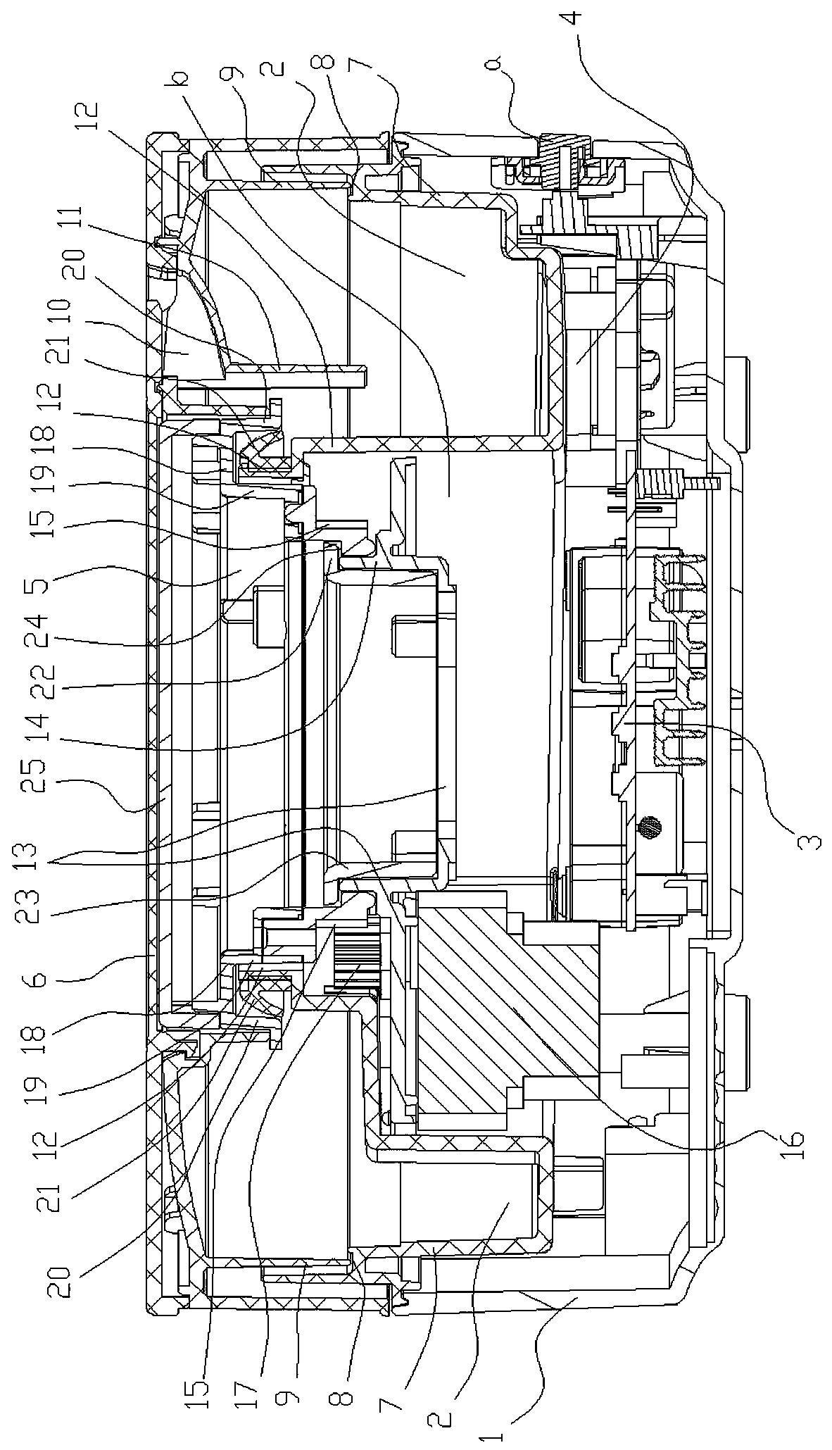
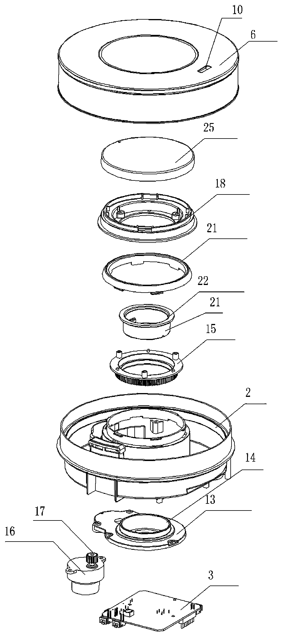
[0012] Now in conjunction with accompanying drawing and embodiment the present invention is described in further detail:

[0013] Such as figure 1 , 2 As shown, the present invention comprises a casing 1 with a control button a, an annular sink 2 arranged in the casing 1, a circuit board 3 (control device) arranged in the casing 1 below the sink 2, and a The atomizer 4 (ultrasonic generator) at the bottom of the water tank 2, the rotating table 5 driven by electric power provided on the perforation b in the middle of the circular water tank 2, the cover 6 provided on the rotating table 5, and the The upper end of the outer groove wall 7 of 2 is provided with an annular groove 8 with a notch upward, and an annular water retaining wall 9 is arranged under the cover 6 corresponding to the annular groove 8, and the bottom surface of the annular water retaining wall 9 extends Into the annular groove 8, the cover 6 is provided with a mist outlet 10 connected with the annular water...


PUM


Abstract

The invention discloses an aromatherapy machine with a rotating structure. The machine is characterized by comprising a machine housing, a circular water groove formed in the machine housing, an atomizer arranged at the bottom of the water groove, a rotary platform driven by electric power arranged on a middle through hole formed in the circular water groove and covers arranged on the rotary platform, a circular groove with an upward opening is formed in the upper end of the outer groove wall of the circular water groove, a circular water blocking wall is arranged on the lower surface of the corresponding cover of the circular groove, the bottom surface of the circular water blocking wall extends into the circular groove, a mist outlet communicated with the circular water groove is formedin the upper surface of the cover, the cover below the mist outlet is provided with water blocking bars extending into the circular water groove straightly, and the lower portions of the water blocking bars are close to the inner groove wall of the circular water groove. Compared with the prior art, the machine has the advantages that the spraying out of small drips along with water mist and insufficient kinetic energy of water mist spraying can be effectively prevented to facilitate the giving off of fragrance.

Description

Technical field: [0001] The invention relates to an atomization technology. Background technique: [0002] The principle of perfume atomization in the existing aromatherapy machine is to atomize the perfume in the water tank through the ultrasonic generator, and then separate the water mist from the water droplets through the separation structure, and the water droplets fall back into the water tank, while the water mist is sprayed through the outlet. The separation structure adopts a static structure, the water droplets are blocked by the cap-shaped blocking structure, and the water mist passes through the cap-shaped perforation to guide the outlet on the top. The direction of spraying is consistent, so the kinetic energy of water mist spraying is relatively large, so that the amount of mist is relatively large, and secondly, some small water droplets will inevitably be entrained in the water mist, which not only wastes perfume, but also affects the fragrance of perfume In...

Claims


Application Information

Patent Timeline
Patent Type & Authority Applications(China)
IPC IPC(8): A61L9/14
CPCA61L9/14A61L2209/13
Inventor 邓伟滔
Owner GUANGDONG FOGGER ELECTRONICS CO LTD
Why Eureka
Try Eureka