
Quantitative water inflow energy-saving boiler

A boiler and water inlet technology, applied in water heaters, fluid heaters, mechanical equipment, etc., can solve the problems of high energy consumption, inconvenient use, and poor constant temperature effect, so as to save electric energy and avoid trouble and inaccuracy , easy-to-use effects

Inactive Publication Date: 2018-08-31
河南硕之家环保科技有限公司
View PDF0 Cites 0 Cited by
  • Summary
  • Abstract
  • Description
  • Claims
  • Application Information

AI Technical Summary

Problems solved by technology

[0002] At present, boilers can be divided into electric hot water boilers, oil-fired hot water boilers, gas hot water boilers, coal-fired hot water boilers, etc. according to different fuels; according to whether they are under pressure, they can be divided into atmospheric pressure hot water boilers and pressure hot water boilers. , our common boilers refer to atmospheric hot water boilers. Due to their safe operation, people mostly use this kind of atmospheric hot water boilers for bathing or heating. However, the current boilers consume a lot of energy during work, while the previous The constant temperature effect is not good, and the water temperature is prone to fluctuate, which brings inconvenience to people's use.

Method used


Image

  • Quantitative water inflow energy-saving boiler
  • Quantitative water inflow energy-saving boiler

Examples


Embodiment Construction

[0017] In order to make the technical means, creative features, goals and effects achieved by the present invention easy to understand, the present invention will be further described below in conjunction with specific embodiments.

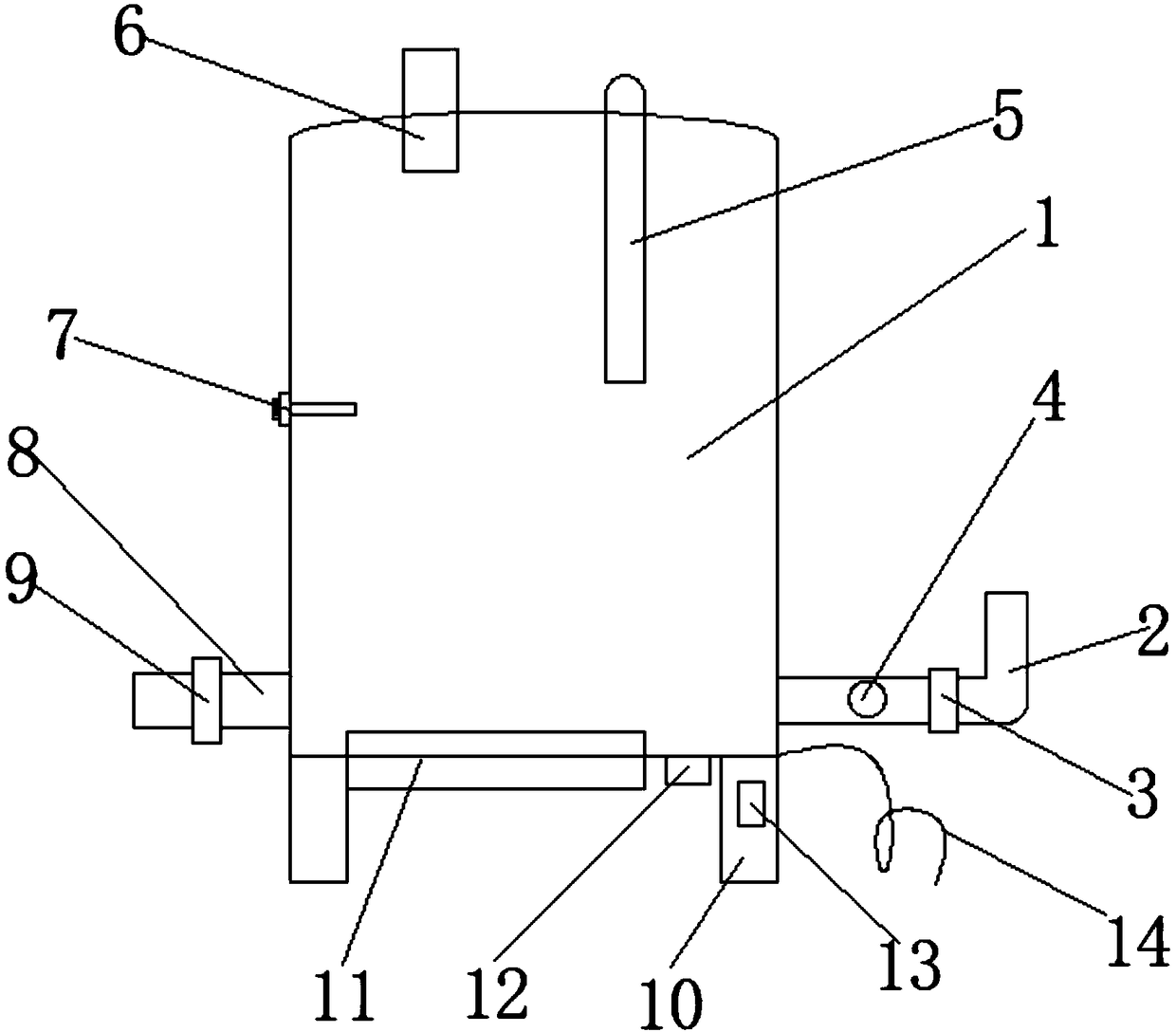
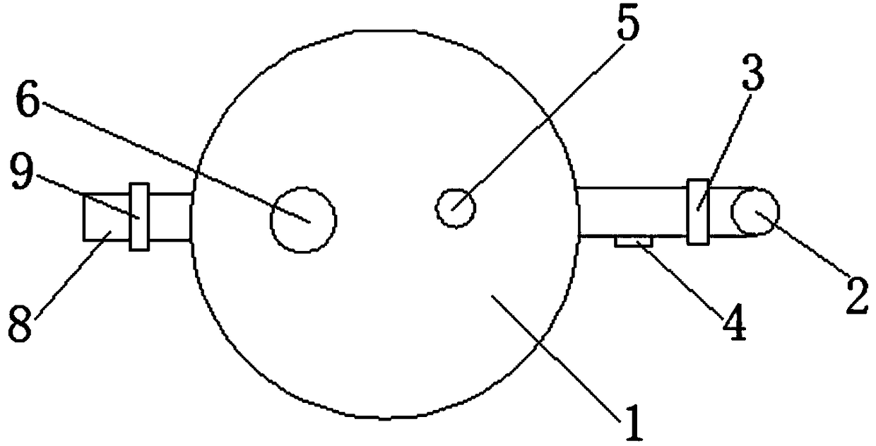
[0018] Such as Figure 1-2 As shown, the quantitative water inlet energy-saving boiler includes a boiler 1, a water inlet pipe 2, an outlet pipe 8 and a bracket 10, the water inlet pipe 2 is installed at the lower right side of the boiler 1, and the water outlet pipe 8 is installed at the left lower end of the boiler 1, The four corners of the bottom of the boiler 1 are equipped with brackets 10, the right side of the inlet pipe 2 is equipped with a solenoid valve A3, the left side of the solenoid valve A3 is equipped with a flow meter 4, and the outlet pipe 8 is equipped with a solenoid valve B9. The models of the battery valve A3 and the solenoid valve B9 are DN50, an outlet pipe 6 is installed on the left side of the upper end of the boiler 1, ...


PUM


Abstract

The invention discloses a quantitative water inflow energy-saving boiler. The quantitative water inflow energy-saving boiler comprises a boiler body, a water inflow pipe, a water outflow pipe and supports; the water inflow pipe is installed at the lower end of the right side of the boiler body; the water outflow pipe is installed at the lower end of the left side of the boiler body; the four corners of the bottom of the boiler body are each provided with the corresponding support; an electromagnetic valve A is installed on the right side of the water inflow pipe; a flow meter is installed on the left side of the electromagnetic valve A; an electromagnetic valve B is installed on the water outflow pipe; the models of the electromagnetic valve A and the electromagnetic valve B are DN; the left side of the upper end of the boiler body is provided with a gas outflow pipe; a control switch is installed above each support; and a power source line is installed at the upper end of the right side of each support. According to the quantitative water inflow energy-saving boiler, the water level in the boiler body is detected through a rod floating ball liquid level switch, when the water level in the boiler body reaches a set value, the rod floating ball liquid level switch can control the electromagnetic valve A to be closed, and therefore it is cut off that a water source centers the boiler body, quantitative water inflow is achieved in the using process of the boiler body, practicability is high, and the quantitative water inflow energy-saving boiler is suitable for wide using andpopularizing.

Description

technical field [0001] The invention relates to a boiler, in particular to a quantitative water-inflow energy-saving boiler. Background technique [0002] At present, boilers can be divided into electric hot water boilers, oil-fired hot water boilers, gas hot water boilers, coal-fired hot water boilers, etc. according to different fuels; , our common boilers refer to atmospheric hot water boilers. Due to their safe operation, people mostly use this kind of atmospheric hot water boilers for bathing or heating. However, the current boilers consume a lot of energy during work, while the previous The constant temperature effect is not good, and the water temperature is prone to fluctuations, which makes it inconvenient for people to use. Therefore, we propose a quantitative water-inflow energy-saving boiler. Contents of the invention [0003] The main purpose of the present invention is to provide an energy-saving boiler with quantitative water inlet, which can effectively s...

Claims


Application Information

Patent Timeline
IPC IPC(8): F24H1/22F24H9/12F24H9/16F24H9/18F24H9/20
CPCF24H1/22F24H9/16F24H9/1809F24H9/2007F24H9/13
Inventor 陈世光陈平旭贾晶
Owner 河南硕之家环保科技有限公司
Learn More