
Rove vertical transmission feeding and spinning device and method

A technology of roving and clutch device, applied in the field of spinning, can solve the problems of low cost of transformation, poor evenness of yarn evenness, and inability to control fibers well.

Active Publication Date: 2018-08-31
ANHUI HANLIAN TEXTILE CO LTD
View PDF7 Cites 4 Cited by
  • Summary
  • Abstract
  • Description
  • Claims
  • Application Information

AI Technical Summary

Problems solved by technology

The modification cost of this method is lower and the efficiency is higher, but the evenness of yarn dryness is poor
In view of this, in the Chinese patent "Segment Color Spinning Transmission Device (Patent No.: ZL200420081737.2)", a segment color yarn production device with four loops is given, but the device still uses double roving feeding, and at the same time , the first roller and the second roller are still controlled by the same motor, so the main draft cannot be adjusted freely
At the same time, in the current spinning process, the rollers are rotated to drive the rubber rollers in close contact with them to rotate, and then the roving is pressed and fed between the rollers and the rubber rollers. Since the rollers are made of iron or steel , so although it can achieve excellent fast transmission when it actively drives the rubber roller of soft material, but in this transmission process, friction will be generated on the surface of the roller of steel or iron hard material, because the fiber is Flexible soft material with elasticity and therefore not able to control the fibers very well, especially when the fed roving has a high twist coefficient

Method used


Image

  • Rove vertical transmission feeding and spinning device and method

Examples


Embodiment Construction

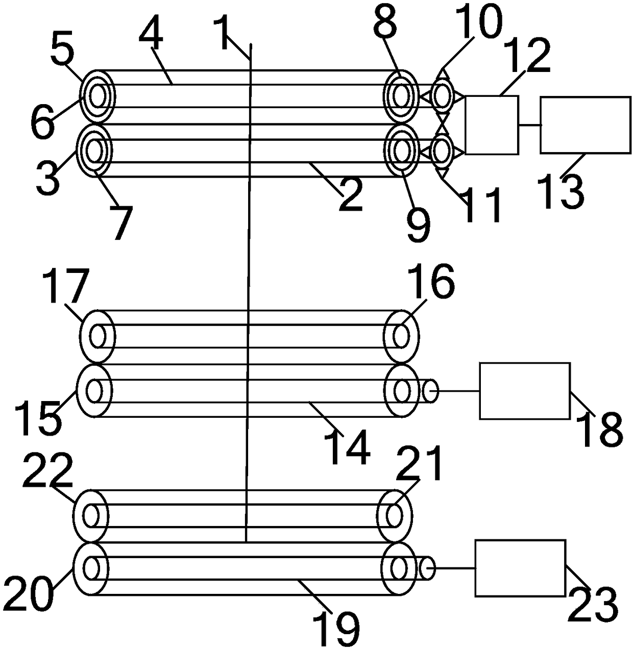
[0017] like figure 1 Shown is a roving feeding spinning device with up and down transmission, including a rear draft roller pair composed of a rear roller and a rear rubber roller, a middle draft roller pair composed of a middle roller and a middle rubber roller, a front roller and a front rubber roller. The front drafting roller pair consists of rollers.

[0018] The rear roller includes a rear roller shaft 2, which is a solid cylindrical structure, and a rear roller sleeve 3 is sleeved on the rear roller shaft 2 on each spindle position, and the left and right ends of the rear roller sleeve 3 respectively pass through the lower left bearing 7 and the lower right bearing 9 are connected with the back roller shaft 2, the lower left bearing 7 and the lower right bearing 9 are release bearings, and the lower left bearing 7 and the lower right bearing 9 are jointly controlled by the first switch to be in an engaged state or in a separated state. When the lower left bearing 7 and...


PUM


Abstract

The invention provides a rove vertical transmission feeding and spinning device and method. The spinning device comprises a rear drafting roller pair composed of a rear roller and a rear rubber roller, a middle drafting pair composed of a middle roller and a middle rubber roller and a front drafting pair composed of a front roller and a front rubber roller. The rear roller adopts a roller sleeve which is connected to a roller shaft through a separating bearing, the rear rubber roller adopts a rubber roller sleeve which is connected to a rubber roller shaft through a separating bearing, and retractable gears with retractable teeth on the surfaces are installed at head ends of the rubber roller shaft and roller shaft. Separate servo motors are connected with the retractable gears through gear groups, so that optional driving of the rubber roller shaft and the roller shaft is achieved, selection between active feeding of rove under driving of the roller sleeve and active feeding of the rove under driving of the rubber roller sleeve is achieved, selection of vertical transmission feeding of the rove according to different rove features is correspondingly achieved, and thus optimized selection of a spinning process is achieved.

Description

technical field [0001] The invention belongs to the technical field of spinning, and in particular relates to a spinning device and a spinning method for feeding and feeding roving up and down. Background technique [0002] With the continuous advancement of the times, people's requirements for clothing materials continue to increase. At present, the textile and clothing industry is in an era of pursuing fashion, diversification and high quality. Therefore, new requirements have been put forward for the development of textile raw materials, among which fancy yarns have gradually entered people's field of vision and occupy an irreplaceable position. Fancy yarn refers to the yarn with special structure and appearance effect obtained by processing fiber or yarn with special raw materials, special equipment or special technology in the process of spinning and thread making. It is a decorative yarn in yarn products. A kind of yarn that works. Fancy yarn has unique structure, fl...

Claims


Application Information

Patent Timeline
IPC IPC(8): D01H5/22D01H5/80D01H13/04
CPCD01H5/22D01H5/80D01H13/04
Inventor 苏旭中刘新金谢春萍徐伯俊宋娟
Owner ANHUI HANLIAN TEXTILE CO LTD
Learn More