An anti-sway device for a crane

A crane and anti-sway technology, applied in the directions of transportation and packaging, load hanging components, etc., can solve the problems of excessive support arm weight and force arm, single-dimensional anti-sway, and large crane gravity, etc., to reduce the difficulty of lifting, Wide hoisting space and the effect of suppressing shaking

Active Publication Date: 2019-08-27
YANSHAN UNIV
View PDF10 Cites 1 Cited by
  • Summary
  • Abstract
  • Description
  • Claims
  • Application Information

AI Technical Summary

Problems solved by technology

The existing technology is still unable to propose a better electric solution for the anti-sway modification of the ship crane
Patent US6439407B1 proposes to use a single slider for lifting, and add two anti-sway ropes on the side of the slider, and then connect the weight to the bottom of the slider through a six-degree-of-freedom parallel rope mechanism. The disadvantage is that the part that needs to be controlled Too many, and the six-degree-of-freedom parallel rope pull mechanism itself requires a certain amount of space
Patent EP2526042B1 proposes a crane that can prevent shaking along the direction of the boom and its vertical direction. Its disadvantage is that the lifting part cannot adapt to the narrow cargo storage environment; patent CN201621218272. The disadvantage is that the weight and force arm of the support arm at the end of the multi-stage movable arm are too large, occupying space, and can only prevent shaking in a single dimension
Patent CN105621275A proposes a crane using a parallel mechanism to prevent shaking. It adds a three-branch parallel mechanism under the crane. The disadvantage is that the gravity of the crane is too large, and the output requirements for the parallel mechanism are relatively high.
Patent US7367464B1, which proposes a crane that uses two rotating beams to control and prevent heavy objects from shaking in the direction of the boom. The disadvantage is that it can only prevent shaking in one dimension

Method used


Image

  • An anti-sway device for a crane
  • An anti-sway device for a crane
  • An anti-sway device for a crane

Examples


Embodiment 1

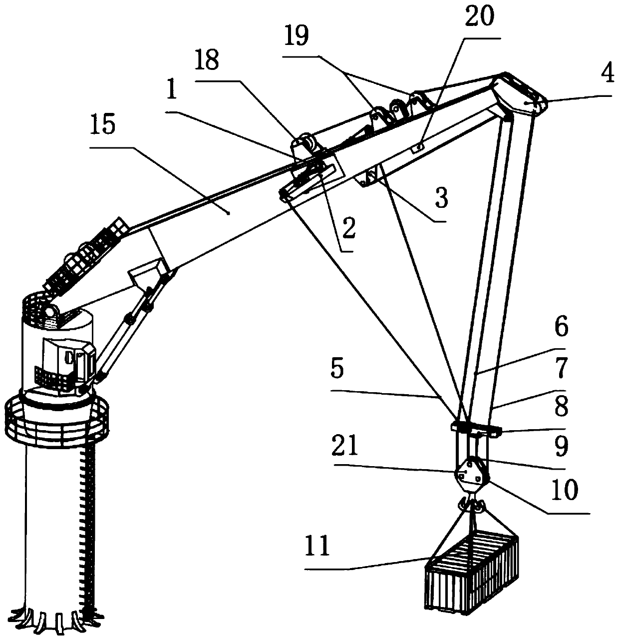
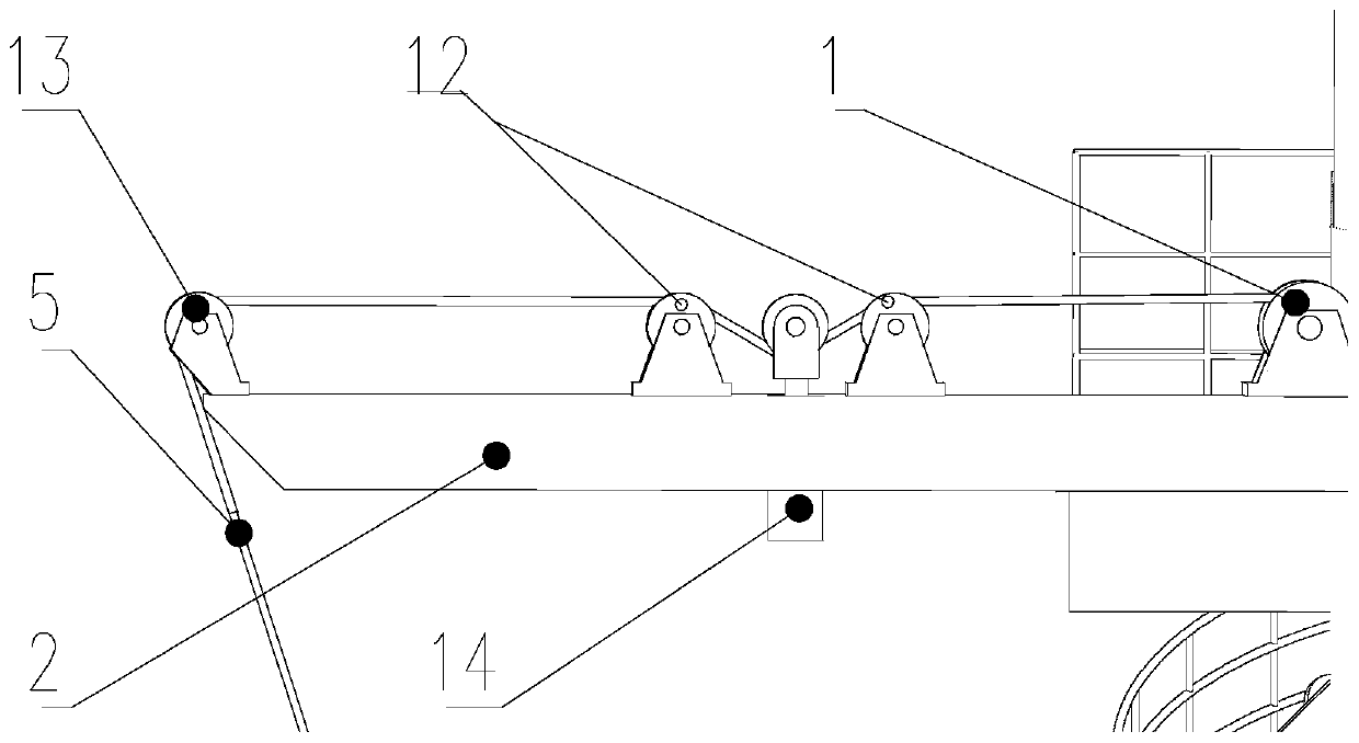
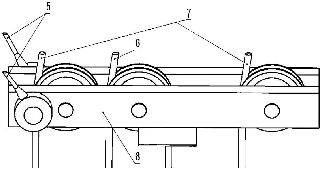
[0030] exist figure 1 In the schematic diagram of the anti-shake device of the crane shown, the pull block 8 is a rectangular frame, such as image 3 As shown, three pulleys with the same structure are sequentially arranged in a rectangular frame through shafts, and the moving block pulley 9 and two load pulleys 10 are jointly arranged on the hook to form a pulley block, such as Figure 5 Shown; The drag cable driving device 3 in the drag cable mechanism is located at the bottom of the middle part of the crane boom 15, and one end of the drag cable 6 is fixed on the winch of the drag cable driving device, and its other end is drawn from the drag cable driving device, bypassing The fixed pulley located under the load cable driving device 4 at the top of the crane arm bypasses the pulley in the middle of the pull block, then bypasses the movable pulley of the pull block, and is finally fixed on the rectangular frame of the pull block;

[0031] The fixed pulley 18 at the end of ...

Embodiment 2

[0040] Such as Figure 6 , Figure 7 and Figure 8 As shown, the pull block 8 is a rectangular frame, two pulleys with the same structure are arranged side by side in the rectangular frame through the shaft, two load pulleys 10 with the same structure are arranged on the hook 21, and the cable drive device 3 in the cable mechanism Located below the middle part of the crane arm 15, one end of the cable 6 is fixed on the winch of the cable drive device, and the other end is drawn out from the cable drive device 3, bypassing the fixed pulley located under the front part of the crane arm, Pass through the pulley on the left side of the pull block, then pass through two load pulleys 10, and finally be fixed on the rectangular frame of the pull block; At the front of the crane arm, the lower end of the cylinder of the load cable actuator in the load cable actuator is fixedly connected to the crane arm, the upper end of the cylinder is connected to the lower end of the load cable a...

Embodiment 3

[0045] Such as Figure 9 As shown, a column is provided on the base of the crane, and a pair of hoisting cable drive devices are provided at the top of the column, and one end of the two hoisting cables 16 is respectively drawn from the two hoisting cable drive devices at the top of the column, and the other ends are respectively Be fixed on the top of both sides of the front part of the crane arm, one end of the two wing-shaped support frame load-bearing cables 17 is fixedly connected with the middle part of the hoisting cable respectively, and its other end is connected with the two ends of the wing-shaped support frame 2 respectively. The boom of the crane is lifted by the hoisting cable, and the left and right wing-shaped support frame load-bearing cables are used to balance the tension of the wing-shaped support frame by the drag cables, reduce the deformation of the wing-shaped support frame, and make the force more reasonable.

[0046] Other components and connection me...


PUM


Abstract

The invention relates to a waggle-preventing device for a crane. The waggle-preventing device for the crane comprises an inhaul cable mechanism, a loading cable mechanism, a towing cable mechanism, aloading cable actuating device, a towing cable actuating device, a pulling block, a pulling block movable pulley and a loading pulley, wherein the loading cable mechanism comprises a loading cable fixed pulley, a loading cable pinch roller, a loading cable actuating device, a loading cable driving device and a loading cable; the towing cable mechanism comprises a towing cable driving device, a wing-shaped supporting rack, a towing cable, a towing cable pinch roller, a towing cable fixed pulley and a towing cable actuating device; the inhaul cable mechanism, the loading cable mechanism and thetowing cable mechanism jointly control the position of a weight in a space, and waggle of the weight is inhibited synchronously depend on a loading cable actuator and two towing cable actuators on thewing-shaped supporting rack. The waggle-preventing device for the crane provided by the invention is large in load and wide in hoisting spatial domain, can play a role of reducing waggle of the hoisted weight along the direction vertical to a lazy arm and the direction of the lazy arm quickly to a great extent, and can meet the demands in a long and narrow cargo placing environment.

Description

technical field [0001] The invention relates to a marine crane, in particular to a crane anti-sway device. Background technique [0002] The marine crane can realize the transfer of goods between ships, and is an important equipment to improve my country's maritime material security and transportation capabilities. Affected by sea waves and sea wind, the hull itself undergoes six-dimensional motions such as rolling and pitching. The disturbance of the cargo by the characteristic wind force causes the cargo under the flexible rope of the crane to sway in space due to inertia, and this phenomenon is particularly prominent when the sea condition deteriorates. Therefore, there is an urgent need to transform or improve the anti-shake technology of traditional cranes. The existing technology is still unable to propose a better electric solution for the anti-sway modification of the ship crane. Patent US6439407B1 proposes to use a single slider for lifting, and add two anti-sway...

Claims


Application Information

Patent Timeline
Patent Type & Authority Patents(China)
IPC IPC(8): B66C13/06
Inventor 赵铁石王唱徐扬赫边辉李二伟胡强强李威
Owner YANSHAN UNIV
Why Eureka
Try Eureka