Hall circuit board fixing structure

A technology for fixing structures and circuit boards, applied in structural connections, shape/style/structure of winding insulation, electrical components, etc., can solve problems such as inconvenient installation methods, cumbersome processes, and low efficiency, and achieve fast installation speed and reduce obstacles Interference and cost reduction effects

Pending Publication Date: 2018-08-28
WOLONG ELECTRIC GRP CO LTD +1
View PDF10 Cites 2 Cited by
  • Summary
  • Abstract
  • Description
  • Claims
  • Application Information

AI Technical Summary

Problems solved by technology

[0002] At present, there are basically two ways to fix the Hall circuit board of the brushless DC motor. One is that the Hall circuit board is directly bound to the coil with the stator core of the winding. position, but the binding process is cumbersome and the efficiency is very low. Another way is to install the Hall circuit board on the end cover. When entering, it is necessary to consider its relative position correspondence to ensure the sensing position of Hall, therefore, there are inconveniences in these two installation methods
[0003] In addition, the insulation between the stator core coil and the stator core of the brushless DC motor is basically realized by insulating paper, and the size of the insulating paper is completed by cutting. Since the insulating paper is relatively soft, it is easy to move when winding the wire bit, which eventually leads to the voltage resistance problem of the stator core of the winding

Method used


Image

  • Hall circuit board fixing structure
  • Hall circuit board fixing structure
  • Hall circuit board fixing structure

Examples


Embodiment Construction

[0031] The technical solution of the present invention will be further described in detail below in conjunction with the accompanying drawings.

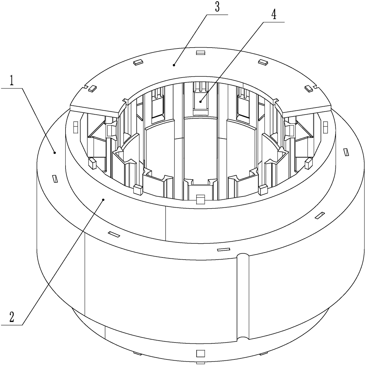
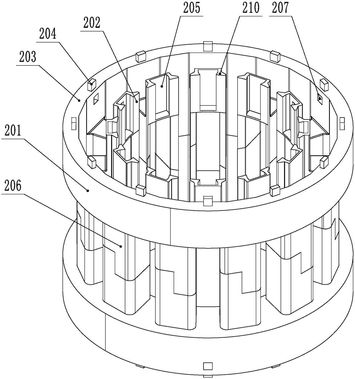
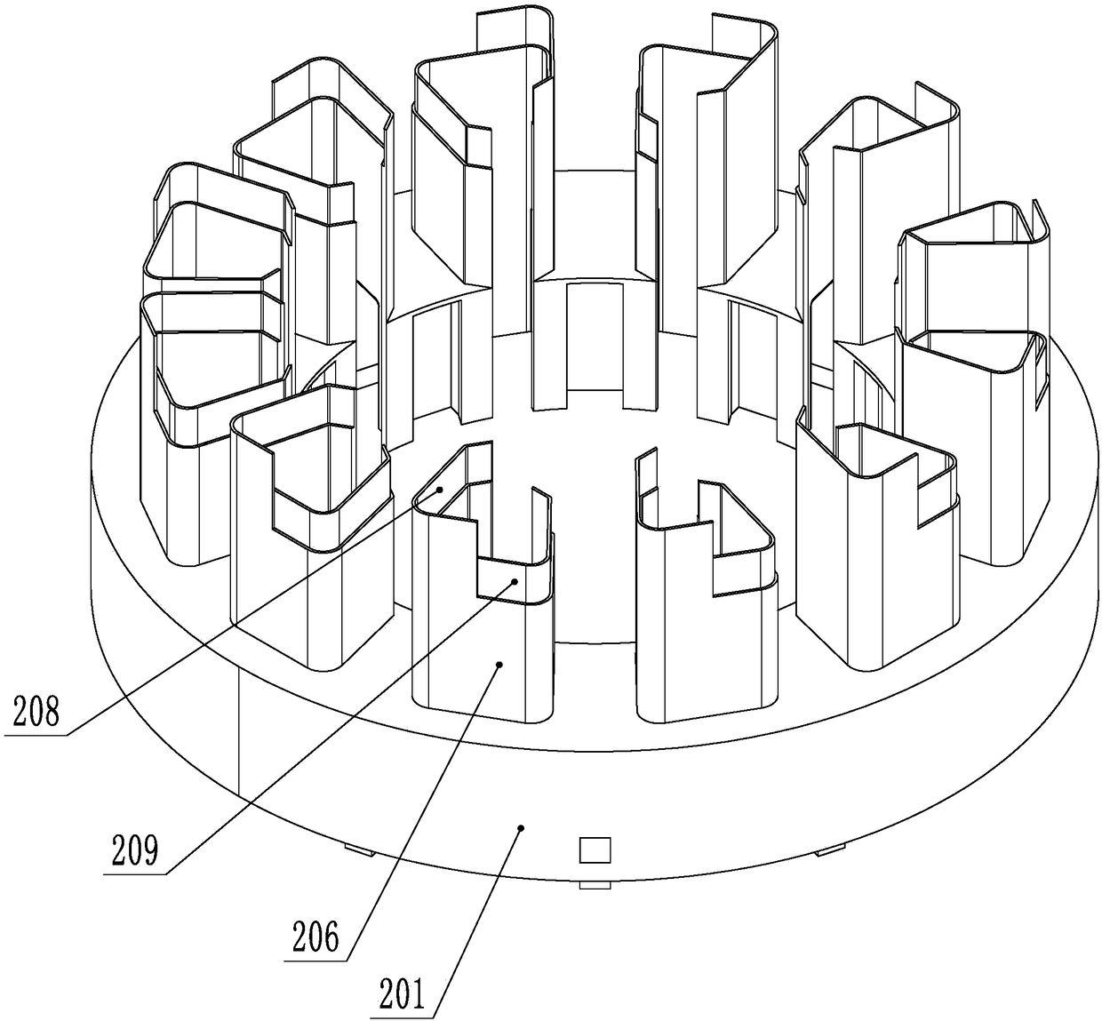
[0032] like Figure 1-3 As shown, a Hall circuit board fixing structure, the Hall circuit board is set on the stator core, the stator core 1 is provided with yokes, teeth and slots, the inner side between the teeth is the opening of the slots, and the stator core is provided with Fixed frame 2, the Hall circuit board is fixed on the fixed frame 2, the fixed frame 2 is provided with the positioning installation structure of the Hall circuit board 3, the mounting frame 202 for positioning and installing the Hall 4 and is used to isolate the stator iron The insulating slot cover 206 of the core 1 and the winding coil, the insulating slot cover 206 covers the inner surface of the yoke, the side surfaces of the teeth and the upper and lower end surfaces, so that the slot is isolated from the yoke and the teeth, and opens at the opening of...


PUM


Abstract

The invention relates to a Hall circuit board fixing structure, and relates to the field of motors. Currently, a fixing mode of a brushless DC motor Hall circuit board is troublesome in installation.A Hall circuit board is disposed on a stator core, wherein the stator core is provided with a yoke, teeth and a slot hole, and an inner side between the teeth is a slot opening. The stator core is provided with a fixed frame. The Hall circuit board is fixed on the fixed frame, and the fixed frame is provided with a positioning and mounting structure of the Hall circuit board, a mounting frame forpositioning and mounting a Hall, and an insulating slot hole sleeve for isolating the stator core and a winding coil. The insulating slot hole sleeve covers the inner side surface of the yoke and theside surface and upper and lower end surfaces of the teeth, so that the slot hole is separated from the yoke and the teeth, and is opened at the slot opening. The structure improves the insulating property between a winding stator iron core coil and the stator core, is convenient to install, is firm in structure, and is good in stability.

Description

technical field [0001] The invention relates to the field of motors, in particular to a Hall circuit board fixing structure. Background technique [0002] At present, there are basically two ways to fix the Hall circuit board of the brushless DC motor. One is that the Hall circuit board is directly bound to the coil with the stator core of the winding. position, but the binding process is cumbersome and the efficiency is very low. Another way is to install the Hall circuit board on the end cover. When inserting, it is necessary to consider its relative position correspondence to ensure the sensing position of the Hall, therefore, both installation methods are inconvenient. [0003] In addition, the insulation between the stator core coil and the stator core of the brushless DC motor is basically realized by insulating paper, and the size of the insulating paper is completed by cutting. Since the insulating paper is relatively soft, it is easy to move when winding the wire ...

Claims


Application Information

Patent Timeline
Patent Type & Authority Applications(China)
IPC IPC(8): H02K11/215H02K3/34
CPCH02K3/345H02K11/215
Inventor 卢鹏飞孙鑫
Owner WOLONG ELECTRIC GRP CO LTD
Why Eureka
Try Eureka