Leakage detection device and method for engine front cover assembly

An engine and front cover technology is applied in the field of engine front cover assembly leak detection devices, which can solve the problems of increased procedures, inability to detect the height and parallelism of oil seals, and many detection procedures, saving procedures and labor, and improving machine utilization. efficiency and improve detection efficiency

Pending Publication Date: 2018-08-28
GUANGDONG HONGTU TECHNOLOGY (HOLDINGS) CO LTD
View PDF21 Cites 9 Cited by
  • Summary
  • Abstract
  • Description
  • Claims
  • Application Information

AI Technical Summary

Problems solved by technology

The front cover of the engine needs to be installed with an oil seal. If the oil seal is not installed correctly, the sealing performance of the front cover assembly will be poor, which will cause leakage failures during the use of the car.
[0003] The current leak detection device cannot detect the height and parallelism of the oil seal. In the first case, it is necessary to go through the entire leak detection process to determine the air tightness. There are many detection processes and time-consuming, and it is impossible to determine the cause of the unqualified air tightness. Whether it is caused by the installation height and parallelism of the oil seal; the second case is that the height and parallelism of the installed oil seal meet the safety range of the leakage value of the airtight test, which is used as the detection standard for the oil seal height and parallelism It is too loose and not precise enough. Practice has proved that small defects in the height and parallelism of the oil seal can pass the air tightness test, but it will still cause leakage accidents during subsequent use.
[0004] Moreover, the current air-tightness testing and press-fitting oil seal are carried out by one air-tightness testing machine and one press-fitting oil seal machine respectively. This method requires the production of two special machines, which increases the floor space, increases the process, and requires staffing. Also correspondingly increased, equipment costs and labor costs will increase

Method used


Image

  • Leakage detection device and method for engine front cover assembly
  • Leakage detection device and method for engine front cover assembly
  • Leakage detection device and method for engine front cover assembly

Examples


Embodiment Construction

[0039] In order to make the object, technical solution and advantages of the present invention clearer, the present invention will be further described in detail below in conjunction with the accompanying drawings and embodiments. It should be understood that the specific embodiments described here are only used to explain the present invention, not to limit the present invention. In addition, the technical features involved in the various embodiments of the present invention described below can be combined with each other as long as they do not constitute a conflict with each other. The present invention will be further described in detail below in combination with specific embodiments.

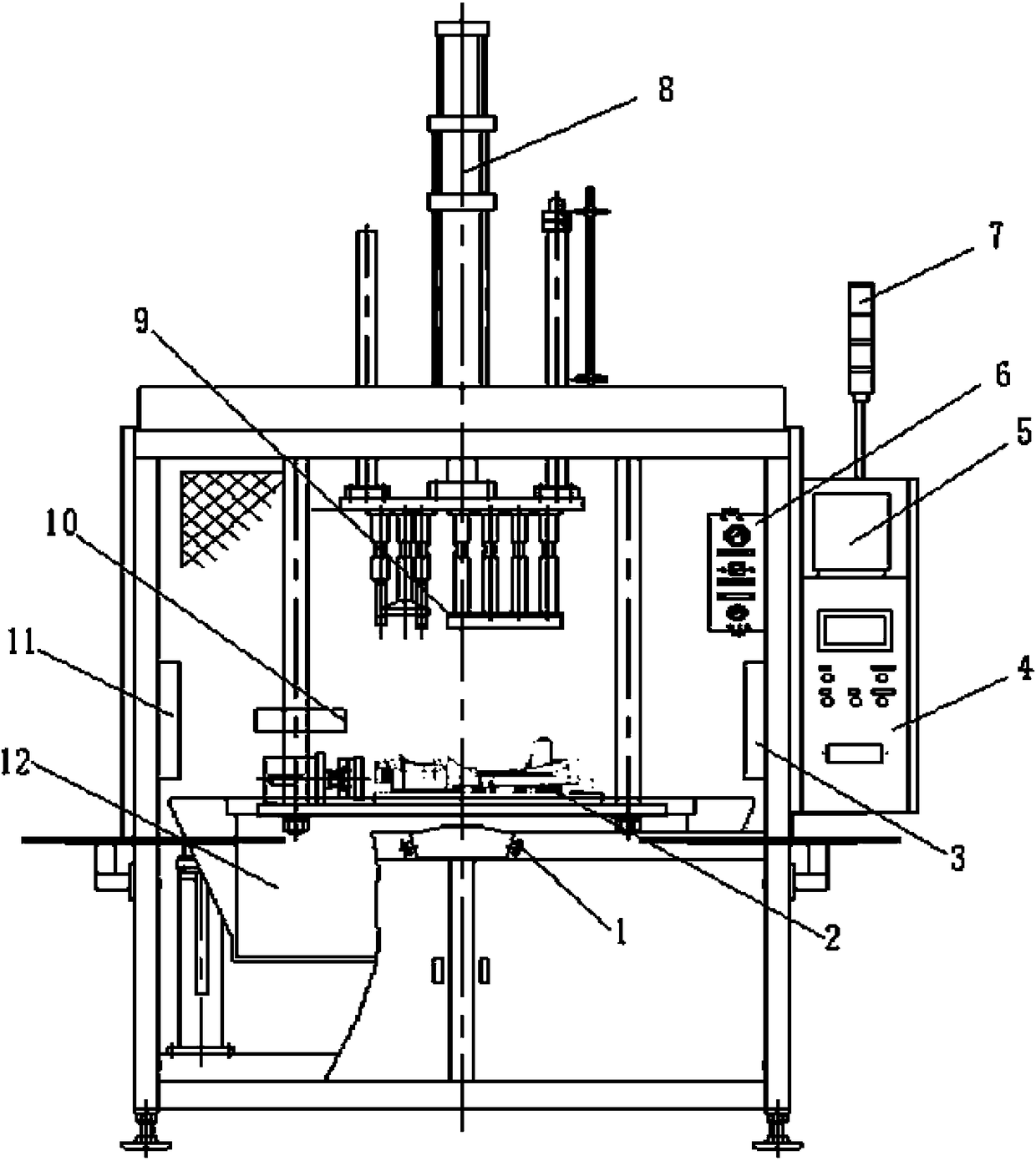
[0040] As a preferred embodiment of the present invention, such as figure 1 As shown, the present invention provides a leak detection device for an engine front cover assembly, which includes a workpiece station, a clamp body, an oil pressure system, a pneumatic system, and an oil seal dete...


PUM


Abstract

The invention discloses a leakage detection device for an engine front cover assembly. The leakage detection device for the engine front cover assembly is characterized by comprising a workpiece station, a clamp body, an oil hydraulic system, a pneumatic system, an oil seal detection device body (10), an air tightness detection device body (5), a water detection system and an electrical system which are arranged on a machine frame body, wherein the oil seal detection device body (10) is provided with a laser distance measuring sensor, and the laser distance measuring sensor is used for measuring the installation height and the depth of parallelism of an oil seal. According to the leakage detection device, the installation size of the oil seal and the air tightness of the front cover assembly can be rapidly and efficiently detected, the overall structure is redesigned and constructed, so that a leakage test tool and a press fitting tool can be further combined, non-interfering operationcan be realized, and therefore air tightness detection and press fitting can be integrated, the structure is simple, the occupied area is small, the utilization rate of a machine table can be improved, and meanwhile, the cost investment can be reduced.

Description

technical field [0001] The invention belongs to the technical field of die-casting equipment, and in particular relates to a leak detection device and method for an engine front cover assembly. Background technique [0002] Nowadays, with the rapid development of the automobile industry, the demand for engine front covers is also increasing. The front cover of the engine needs to be installed with an oil seal. If the oil seal is not installed correctly, the sealing performance of the front cover assembly will be poor, which will cause leakage failures during the use of the car. [0003] The current leak detection device cannot detect the height and parallelism of the oil seal. In the first case, it is necessary to go through the entire leak detection process to determine the air tightness. There are many detection processes and time-consuming, and it is impossible to determine the cause of the unqualified air tightness. Whether it is caused by the installation height and pa...

Claims


Application Information

Patent Timeline
Patent Type & Authority Applications(China)
IPC IPC(8): G01M3/06G01M3/26G01B11/06G01B11/26
CPCG01B11/0608G01B11/26G01M3/06G01M3/26
Inventor 章学良赵善庆卢广英黎烨文吴绍方
Owner GUANGDONG HONGTU TECHNOLOGY (HOLDINGS) CO LTD
Why Eureka
Try Eureka