Pneumatic road surface power generation system

A road power generation and pneumatic technology, which is applied to machines/engines, mechanisms that generate mechanical power, mechanical equipment, etc., can solve the problem that deceleration facilities cannot collect a large amount of energy from vehicles, and achieve the effect of less comfort

Inactive Publication Date: 2018-08-28
李良杰
View PDF4 Cites 0 Cited by
  • Summary
  • Abstract
  • Description
  • Claims
  • Application Information

AI Technical Summary

Problems solved by technology

[0003] In order to solve the problem that various road surface deceleration facilities cannot collect a large amount of energy lost by vehicles, the present invention provides a pneumatic road surface power generation system

Method used


Image

  • Pneumatic road surface power generation system

Examples


Embodiment Construction

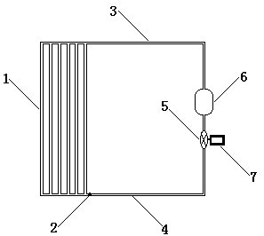
[0009] The aerodynamic road power generation system consists of an airflow conductor (1), an air guide pipe (3), an air pressure chamber (6), an air return pipe (4), a one-way air valve (2), a turbine (5) and a generator (7) , the airflow conductor is composed of multiple air pressure tubes and two pressure surfaces, the air pressure tubes and the upper pressure surfaces are made of elastic materials, and the multiple air pressure tubes are sandwiched between the two pressure surfaces parallel to the straight line where the road surface is located. The air flow guide is installed under the road surface, one end of the air guide pipe is connected to the air pressure pipe, the other end of the air guide pipe is connected to the intake port of the turbine through the air pressure chamber, one end of the return air pipe is connected to the air outlet of the turbine, and the other end of the air return pipe It is connected to the air pressure pipe through a one-way air valve, and th...


PUM


Abstract

The invention discloses a pneumatic road surface power generation system which is composed of an airflow conduction device, an air guide tube, an air pressure cabin, an air return tube, a one-way airvalve and an electric generator, wherein the airflow conduction device is composed of a plurality of air pressure tubes and two pressure surfaces; the air pressure tubes and the pressure surfaces above are made of elastic material; the air pressure tubes and the straight line on which the road surface is positioned are clamped between the two pressure surfaces in parallel; the airflow conduction device is mounted below the road surface; one end of the air guide tube is connected onto the air pressure tubes; the other end of the air guide tube is connected onto the air inlet of a turbine via the air pressure cabin; one end of the air return tube is connected onto the air outlet of the turbine; the other end of the air return pipe is connected onto the air pressure tubes via the one-way airvalve; the rotor of the electric generator is connected onto the shaft of the turbine; the air pressure tubes, the air guide tube and the air return tube are filled with the air; and the one-way air valve only allows the air in the air pressure tubes to move in the driving direction of the road.

Description

technical field [0001] An aerodynamic pavement power generation system. Background technique [0002] At present, in order to prevent traffic accidents caused by the excessive speed of vehicles on certain road sections, various road facilities that affect the rapid progress of vehicles are usually installed on the road. These road facilities often cause a lot of energy to be wasted in vain and cannot be used . Contents of the invention [0003] In order to solve the problem that various road surface deceleration facilities cannot collect a large amount of energy lost by vehicles, the present invention provides an aerodynamic road surface power generation system. The aerodynamic road power generation system uses the gas in multiple air pressure pipes parallel to the straight line of the road surface in the air flow conductor laid under the road surface, and under the rolling action of the wheels, the turbine is driven to rotate to generate electricity, so as to collect the...

Claims


Application Information

Patent Timeline
Patent Type & Authority Applications(China)
IPC IPC(8): F03G7/00F01D15/10
CPCF03G7/00F01D15/10
Inventor 李良杰
Owner 李良杰
Why Eureka
Try Eureka